Page 48
VP-X Installation and Operating Manual
Rev. D (August 5, 2020)
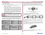
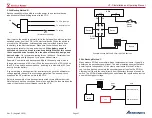
Wire a fuse or fuse block near the battery. Size the fuse for the wires and as
per recommended by the EFIS manufacturer. Then wire to an SPST switch.
The switch should be labeled Auto (down) and On (up). When the switch is
off, power will be sourced from the VP-X. When on, power will be sourced
either directly from the battery bus or the VP-X.
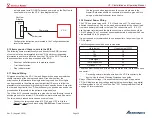
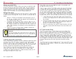
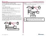
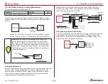
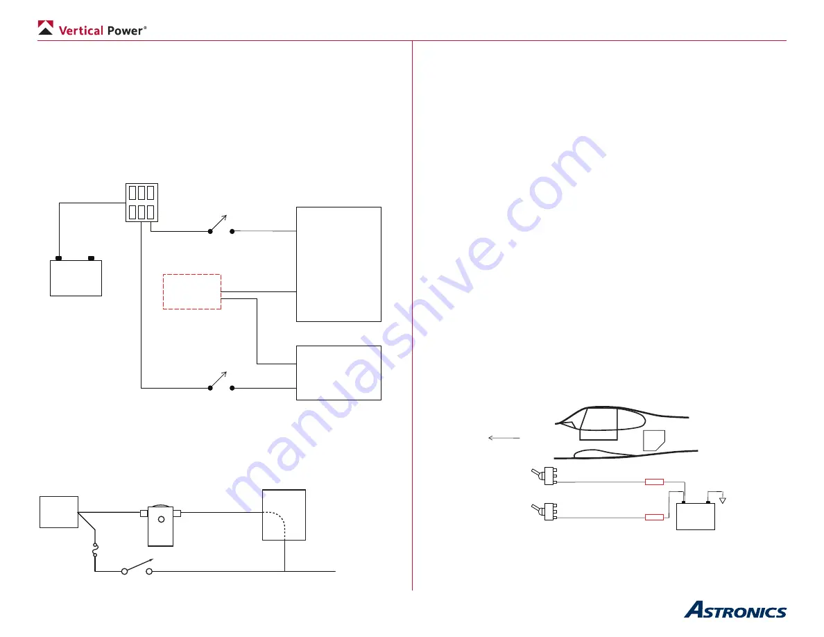
Below is an example of a two backup circuit wired to two different devices.
Note that each backup circuit has its own fuse, and that the fuse matches the
value of the electronic circuit breaker set in the VP-X.
EFIS
2A
2A
5A
5A
+ -
Battery
Fuse Block
Secondary Pwr In
Primary Power In
AHRS
Secondary Pwr In
Primary Power In
SPST
Switch
SPST
Switch
VP-X
Example backup Method C circuit with two devices.
5.24d Do not wire backups this way
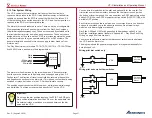
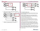
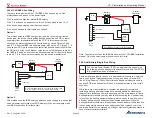
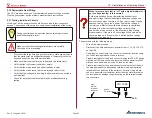
Do not wire other circuits so that battery power is provided directly to the
device, as illustrated in the diagram below.
VP-X
+
Batt
Battery
Contactor
To Device
Do NOT wire backups directly to power output of VP-X.
Doing so may cause unreliable operation and may blow the fuse under
certain circumstances.
5.24e Aft-mounted battery considerations
If the battery in your aircraft is mounted in the aft section of the aircraft, you
must take special care to route the backup switch wiring because the routing
is longer than for front mounted batteries. You may want to consider running
a slightly larger wire to account for the additional length. FAA AC 43.13-1B
includes a chart (figure 11-2) to determine the wire size.
Another consideration is that the relatively long length of wire must be
protected from short circuits. There are two options to choose from:
1. Run each backup wire to the back, and to an individual fuse in a fuse
block. Have a fuse block in back with a short wire (perhaps 12ga) to
the battery. You don’t need to protect the 12ga wire because it is so
short. If a wire running to the front shorts, you lose just that circuit.
2. Run a larger wire from the back to the front. Install a larger fuse in
the back to protect the long run to the front, then smaller fuses in
the fuse block up front for each backup circuit. However, if the larger
fuse blows all the backups fail in one shot.
Keep in mind these are backup circuits and normally only used when the
primary switching method fails. Choose the option that works best for your
mission and personal assessment of merits of each.
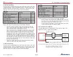
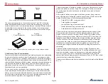
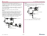
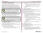
The diagram below shows the relative layout of the backup circuit
components. Note that the fuses (or breakers) are in the back near the
battery, providing protection for the wire run forward.
+ -
Battery
Backup
Switch(es)
Fuse
Or
Fuse Holder
(near battery)
Front


