Page 53
VP-X Installation and Operating Manual
Rev. D (August 5, 2020)
5.30
Retractable Gear Wiring
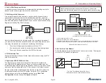
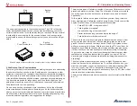
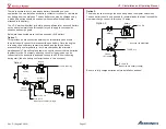
The VP-X provides a source of circuit protected power for the gear switch.
Wire the gear system per the airframe manufacturer’s instructions.
5.31
Testing Individual Circuits
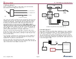
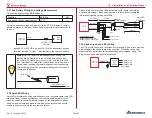
At this point, all the power wires should be connected to their respective
devices. The purpose of this step is to verify correct installation of the wiring.
Taking your time and being methodical on this step will save
troubleshooting time later.
Make sure that the following bulleted items are carefully
checked prior to proceeding.
• Disconnect the large wire going to the starter to eliminate any chance
that the starter may be accidentally engaged. Temporarily cover the
exposed end of the wire with electrical tape.
• Make sure that the propeller area is clear and can rotate freely.
• Verify that the fuel system is sealed or empty.
•
Verify that the area around and under the flaps is clear.
• Verify that the area around the trim motors and tabs is clear.
• Verify the high-voltage strobe wiring is either sealed or connected to
a strobe light.
• Check for any other conditions that may be problematic during
testing.
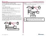
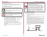
When I measure a pin that is “off” with a digital multimeter, I
get a voltage reading. Is this normal?
Solid-state switches have a characteristic called stray or
phantom voltage that will read slightly below bus voltage on a
power pin even when that pin is off. Don’t worry, it won’t cause
sparks or arcing. There is no “power” behind the voltage, it
is simply an artifact of the solid-state switches (a specialized
transistor). In order to measure voltage correctly, there
needs to be a load on the pin, like a test lamp, when taking
measurements. If the pin is off, the voltage will be zero when
there is a load on it. If the pin is on it will read at bus voltage
when there is a load on it.
Then proceed with the following steps:
• Turn off the master switch.
• Disconnect the wiring harness connectors from J1, J2, J8, J10, J12
on the VP-X.
• Verify that the correct wire is in the correct connector location using
the Load Planning worksheet as a reference.
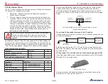
• Prepare test leads for the d-sub connector using two 20 or 22 gauge
wires about 10ft long each with a female d-sub connector terminal
crimped on one end and an in-line 2A fuse on the other.
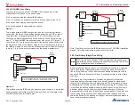
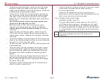
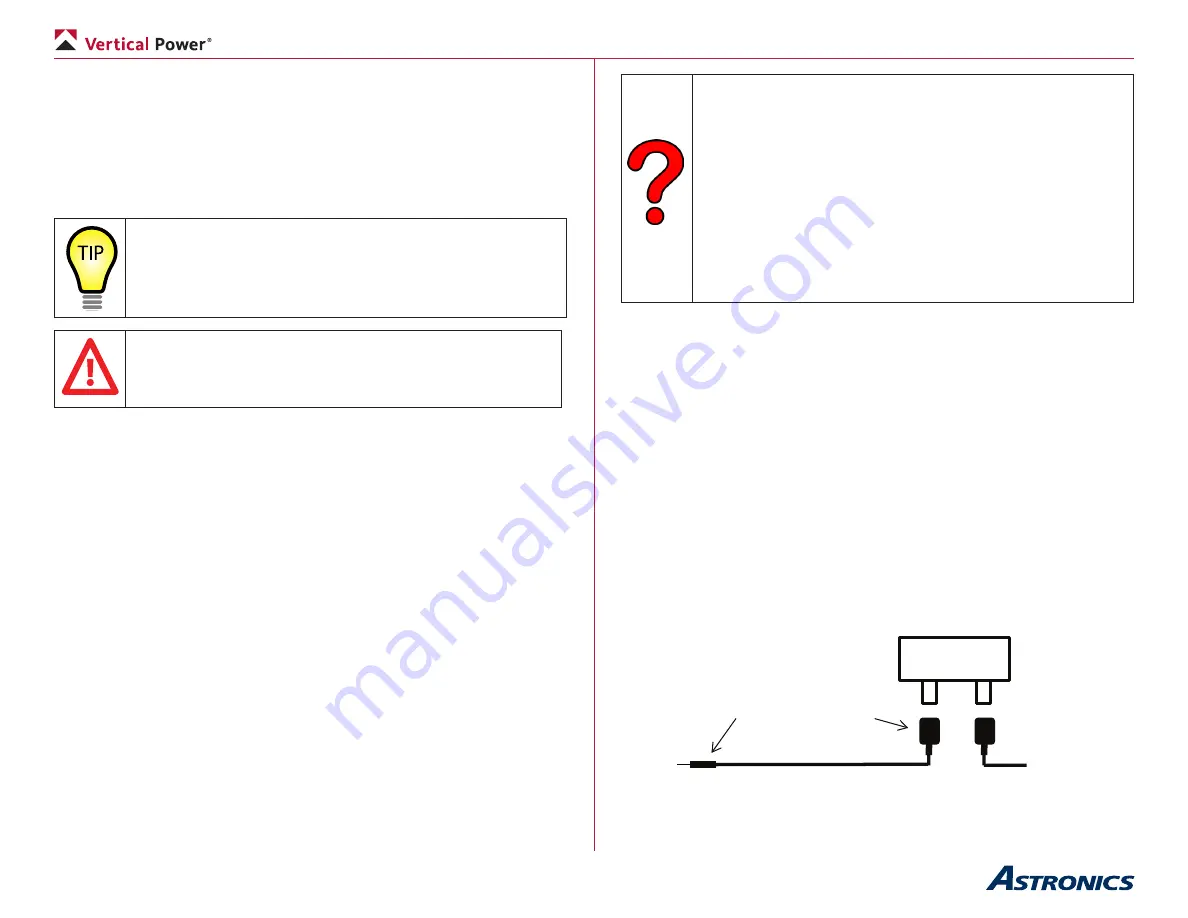
• Prepare test leads for the power connectors using the test leads in
the wiring harness kit, attach spade terminals to an appropriately
rated blade fuse and then to the battery or hot wire. Using a bare-
end wire, paperclip or screwdriver rather than the male terminal on
the test lead may damage the gold coating on the terminals inside
the connectors.
Batt +
ATC FUSE
Spade
Terminals
Male
terminal
for power
connector

