Page 73
VP-X Installation and Operating Manual
Rev. D (August 5, 2020)
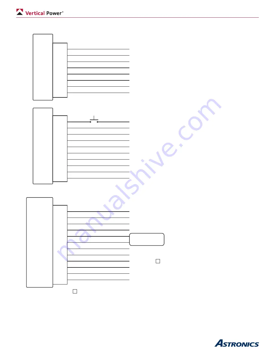
Appendix A1 – J8, J10, J12 Connector Wiring
VP-X
J8
Male
1
2
3
4
5
6
7
8
5A
10A
5A
5A
5A
5A
5A
5A
Device (5A CB max)
Device (10A CB max)
Device (5A CB max)
Device (5A CB max)
Device (5A CB max)
Device (5A CB max)
Device (5A CB max)
Device (5A CB max)
VP-X J10
Male
1
2
3
4
5
6
7
8
9
10
Starter
5A
10A
5A
10A
15A
5A
5A
GND
5A
Starter solenoid (10A CB max)
Device (5A CB max)
Device (10A CB max)
Device (5A CB max)
Device (10A CB max)
Device (15A CB max)
Device (5A CB max)
Device (5A CB max)
Aircraft ground block
Device (5A CB max)
1
1
Start
VP-X J12
Male
REV A
1
2
3
4
5
6
7
8
9
10
11
12
10A
15A
10A
GND
Flap
Flap
10A
5A
EFIS
5A
Alternator
15A
Device (10A CB max)
Device (15A CB max)
Device (10A CB max)
Aircraft ground block
Flap motor
(10A CB max)
Device (10A CB max)
Device (5A CB max)
EFIS power
Device (5A CB max)
Primary alternator field
Device (15A CB max)
Must go to the same EFIS that the serial lines on J1 go to.


