Page 29
VP-X Installation and Operating Manual
Rev. D (August 5, 2020)
5.7 Starter Annunciator Wiring
Function
VP-X Pin
I/O
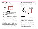
Starter annunciator input
J2-11
I
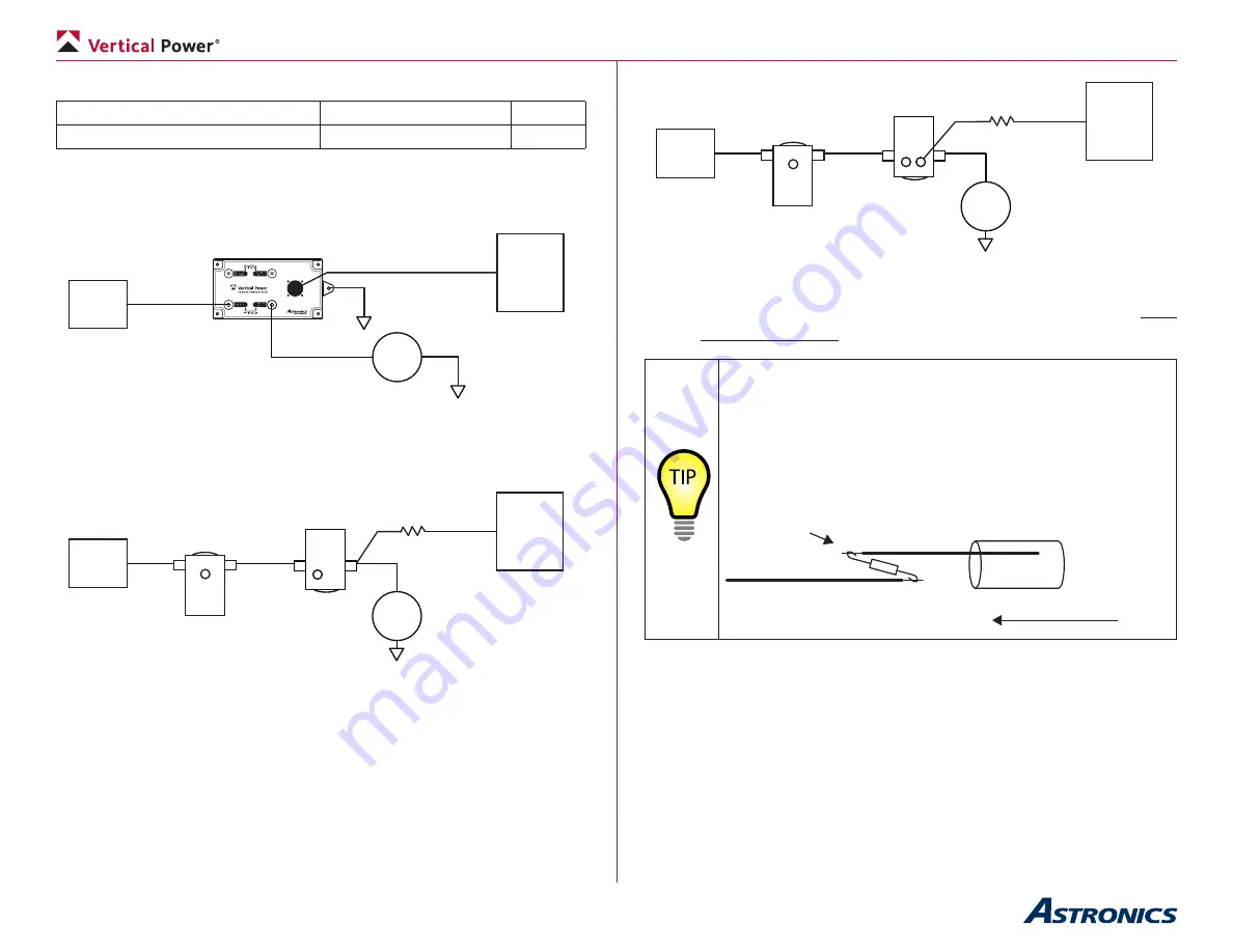
This pin measures voltage on the starter (or switched) side of the starter
contactor and reports it to the EFIS for display. If enabled on the EFIS, an
annunciator appears whenever the starter contactor is engaged.
J2-11
+
Batt
VP-X
STARTER
PPS
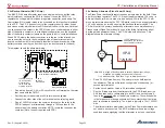
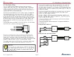
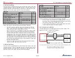
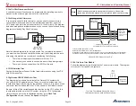
With the PPS, this is a simple connection to J2-11 on the VP-X. In a
conventional system, a resistor should be placed in-line near the contactor to
provide circuit protection for the wire.
1K Ohm, 1W
Resistor
J2-11
+
Batt
VP-X
Starter
Contactor
STARTER
Battery
Contactor
Option 1: Connect wire to switched side of starter contactor
1K Ohm, 1W
Resistor
J2-11
+
Batt
VP-X
Starter
Contactor
S I
STARTER
Battery
Contactor
Option 2: Connect wire to “I” terminal on starter contactor, if it is present.
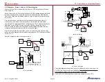
• Install a 20 AWG wire from J2-11 to the switched side of the starter
contactor or “I” terminal. Install a 1K Ohm, 1 watt resistor in-line near
the starter contactor.
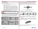
Wiring Tip
: The resistor is a weak spot in the wiring. The
resistor itself is fragile, as is the small lead on either side of
the resistor. To create a more secure joint, use the wire itself
as a reinforcement. Solder the resistor leads onto the wire as
shown below, keeping the resistor leads as short as possible.
After soldering, cover the assembly with heat shrink to keep it
securely held together.
Heat Shrink Tubing
Slide
Solder (2x)
5.8 Other Contactor Wiring
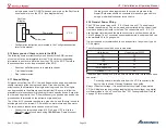
If other contactors (for hydraulic pumps, air conditioning, etc.) are installed in
the aircraft, they must have diodes installed across the coil as shown above.
• Install diodes on the other contactors.


