Page 34
VP-X Installation and Operating Manual
Rev. D (August 5, 2020)
5.10
Primary EFIS Wiring – Power and Data Connections
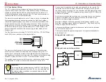
The “primary” EFIS is unique because it is the EFIS that displays the faults
and status from the VP-X.
This EFIS power
must
be wired to J12-9. The
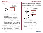
EFIS to which you wire the VP-X serial line must be the same EFIS that
you run the power to J12-9. Note that this pin is ‘always on’ and cannot
be set to a switch assignment.
• Install a 20 AWG wire from J12-9 to the EFIS primary power input.
• If desired, install a backup circuit for the secondary power input on
the EFIS. See “Backup Circuits” section later in this document.
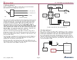
• Connect the three data wires on the VP-X J1-20, 21, 22 to a serial
data port on the EFIS. Typically serial data transmit and receive lines
are grouped together on the EFIS. The transmit line (J1-20) on the
VP-X goes to the receive line on the EFIS. Conversely, the receive
line (J1-22) on the VP-X is wired to the transmit line on the EFIS. The
VP-X communicates at 57600 bits per second.
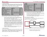
“Which screen should I wire the serial line to?”
Below is our list of recommendations. PFD is the primary flight display
usually right in front of the pilot that shows attitude information, and the MFD
is the secondary display that usually shows maps. If you want to deviate
from this, contact the EFIS manufacturer and ask them if your proposed
configuration is supported.
Advanced Flight Systems: PFD
Dynon SkyView: both
GRT Horizon or Sport: MFD or PFD
Garmin G3X Touch, G3X: MFD or PFD
MGL: PFD
5.11
Advanced Flight Systems EFIS Wiring
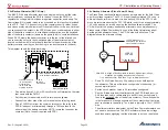
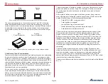
Wire to any serial port on either EFIS (if you have more than one). The VP-X
screen as well as trim and flap position can be seen from any EFIS screen. Use
a serial port pair on the EFIS. Make sure the EFIS and the VP-X are wired to
the same ground. Do not use the serial ground on the VP-X.
5.12 GRT EFIS Wiring
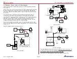
On the HORIZON, trim and flap position are shared on the display interlink
between display, but the status of each electrical device is not. The VP-X
electrical page only appears on the display that is wired to the VP-X. On the
SPORT, no data is shared between the displays, so wire the VP-X serial
line to the display on which you want to see trim and flap position and VP-X
electrical page.
Use a serial port pair on the EFIS. Make sure the EFIS and the VP-X are
wired to the same ground. Do not use the serial ground on the VP-X.
5.13 MGL EFIS Wiring
Use any RS-232 port except for the dedicated NMEA port on the screen you
want to see the list of electrical devices.
5.14 Garmin G3X Wiring
Wire to the MFD on a dual screen system if using a NON-Touch G3X. This
is the screen that will show the electrical devices. The trim and flap position
is displayed on any EFIS screen, but the VP-X electrical page is only shown
on screen with the serial connection. Use a serial port pair on the EFIS,
including the associated serial ground line. If using a G3X Touch, you can
wire to either the PFD or MFD.
5.15
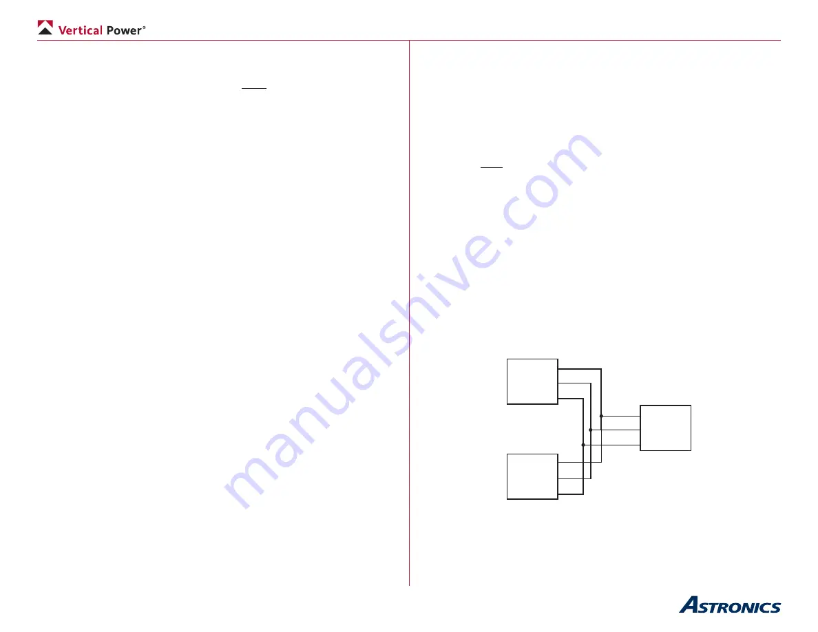
Dynon SkyView Wiring
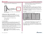
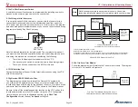
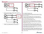
In a dual SkyView installation, split both the transmit and receive lines and
connect to both screens. You will then have a transmit and receive line going
to each screen. The VP-X information (including trim and flap position) only
shows up on the screen(s) to which a serial line pair is connected. Normally
you cannot split the VP-X receive line, but Dynon uses a special schema that
only transmits on one screen at time, so the VP-X only receives from one
screen at a time.
VP-X
SV
PFD
SV
MFD
TX
RX
TX
TX J1-20
J1-22
J1-21
RX
RX
GND
GND
GND
Wiring Diagram Overview (SkyView ONLY)


