Page 52
VP-X Installation and Operating Manual
Rev. D (August 5, 2020)
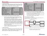
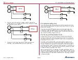
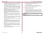
5.27 Aux Battery Wiring and Voltage Measurement
This section applies to the
VP-X Pro
only.
Function
VP-X Pin
I/O
Aux battery voltage measurement
J2-12
I
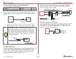
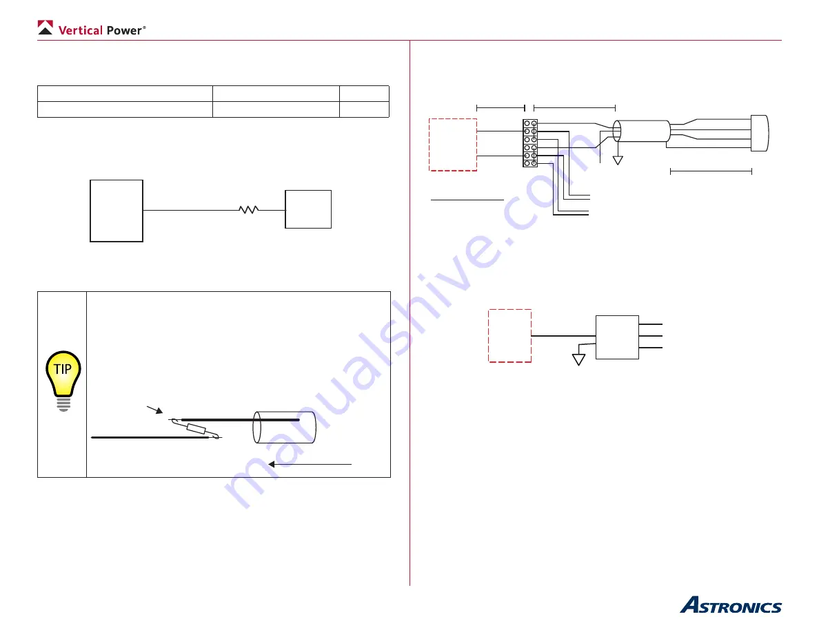
This pin measures voltage and reports it to the EFIS for display. A resistor
should be placed in-line near the aux battery to provide circuit protection for
the wire.
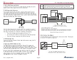
1K Ohm, 1W
Resistor
J2-12
Aux
Batt
+
VP-X
• Install a 20 or 22 AWG wire from J2-12 to the aux battery positive
terminal. Install a 1K Ohm, 1 watt resistor in-line near the battery.
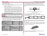
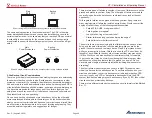
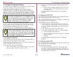
Wiring Tip
: The resistor is a weak spot in the wiring. The
resistor itself is fragile, as is the small lead on either side of
the resistor. To create a more secure joint, use the wire itself
as a reinforcement. Solder the resistor leads onto the wire as
shown below, keeping the resistor leads as short as possible.
After soldering, cover the assembly with heat shrink to keep it
securely held together.
Heat Shrink Tubing
Slide
Solder (2x)
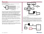
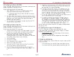
5.28 AeroLEDs Wiring
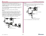
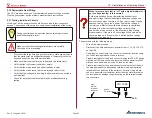
AeroLEDs recommends using shielded power wire for certain lights (AeroLED
makes a “linear” voltage light that does not require shielded cable). If you
need the power connector terminals crimped on the shielded wire, please
send us the wire (strip and prepare shielding on the terminal end prior to
sending) and we will crimp the terminals on for you.
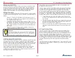
Please follow the latest AeroLEDs instructions with regard to shielding
and case grounding. Please see Appendix E in this manual for detailed
information regarding wiring AeroLEDs.
AeroLED
Nav/Strobe
VP-X
Nav Pwr
<12 inches
20AWG
3 cond, shielded
Circuit breaker sizing
Budget 0.5A per nav light
Budget 2.0A per strobe light
Strobe Pwr
Terminal
Strip
Red
Yellow
Green
Black
Shield
Yellow
Green
(sync)
To other AeroLED
To other AeroLED
Red
Ground
minimal
minimal
5.29
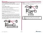
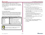
Strobe Light (non-LED) Wiring
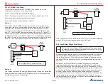
The VP-X provides power to the strobe power supply, which in turn provides
high-voltage to the strobe lights at the wing tips. Follow the strobe light
manufacturer’s instructions for installation and circuit breaker sizing. The
diagram below shows a generic installation.
VP-X
Strobe Pwr
Strobe
Pwr
Supply
(high voltage)
Strobe Light
Strobe Light
Strobe Light

