Page 74
VP-X Installation and Operating Manual
Rev. D (August 5, 2020)
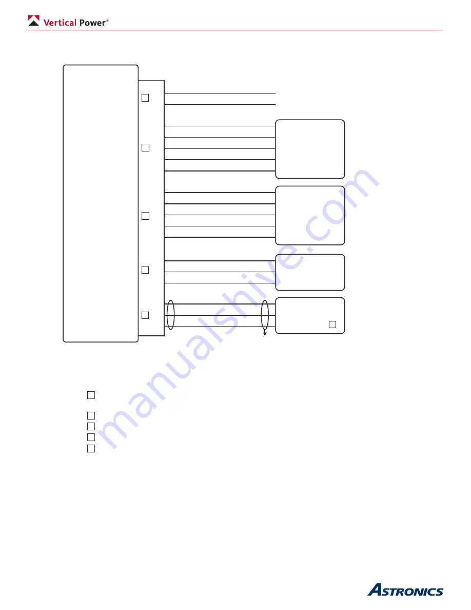
Appendix A2 – J1 Connector Wiring
VP-X
J1
Female
Male
REV A
1
2
3
4
5
6
7
8
9
10
11
12
17
18
19
20
21
22
2A
2A
Roll Trim
Roll Trim
Roll Trim
Roll Trim
Roll Trim
Pitch Trim
Pitch Trim
Pitch Trim
Pitch Trim
Pitch Trim
Flap position
Flap position
Flap position
Serial TX
Serial GND
Serial RX
Use wire M27500-24TG3T14 (3 conductor, 24 AWG, shielded)
Use wire 3 conductor, 24 AWG, unshielded or shielded
2
Serial must be wired to same EFIS that is powered by J12-9.
See instructions in manual for Dynon wiring.
1
1
3
2
Use wire 5 conductor, 24 AWG, unshielded
Use wire M22759/16-22 (22 AWG Tefzel)
5
6
Ray Allen
Trim motor
w/ pos sensor
Device (2A CB max)
Device (2A CB max)
Ray Allen
Trim motor
w/ pos sensor
Ray Allen
POS-12
Position sensor
6
3
5
5
WHT/BLU
WHT/ORN
WHT/GRN
WHT
WHT
WHT/BLU
WHT/ORN
WHT/GRN
WHT
WHT/ORN
WHT/BLU
EFIS
WHT
WHT/ORN
WHT/BLU
WHT
WHT
Serial RX
Serial GND
Serial TX


