EXS
10
User Manual 10H52260UM60 - Rev. 1 - 10/2017
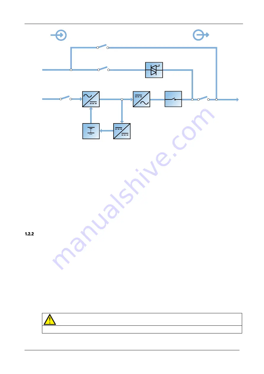
Figure 1-1 Block diagram illustrating the working principle of a UPS single module
The UPS has its own battery charger and adopts advanced temperature compensation technology to effectively
prolong the battery service life. The inverter is principally based on the use of large power IGBTs, and adopts
advanced SVPWM control technology to reconvert the DC bus voltage to AC voltage.
When the mains is normal, the rectifier and inverter work together to supply the loads and charge the battery.
When the mains is outside normal limits, the rectifier stops working, and the battery supplies power to the loads
through the inverter. If the battery voltage falls to end of discharge (EOD) voltage and the mains has not yet
returned within the normal limits, the UPS will shut down (if the system uses split bypass configuration and the
bypass is normal, the system will transfer to bypass). The battery EOD voltage is pre-set. When the mains is
abnormal, the battery will continue to supply the UPS until the battery voltage reaches to EOD level, whereupon the
UPS shuts down; this period is known as the 'Backup Time'. The duration of the backup time depends on the battery
capacity and the loads.
Bypass
Thanks to the intelligent control function provided by the ‘Static Switch’ module (as shown in Figure 1-1), which
includes the controllable electronic switch, the loads may be supplied either by the inverter or the bypass. Under
normal operating conditions, the loads are supplied by the inverter, in which case the automatic inverter switch on
the inverter side is closed. In the event of an overload (after the overload delay period has elapsed) or inverter
failure, the inverter switch is opened, and the 'Static Switch' module transfers the loads automatically to the bypass.
In normal operating state, in order to guarantee the uninterrupted transfer between inverter and bypass, the inverter
output must be synchronized with the bypass.
Therefore, when the bypass frequency is within the synchronization range, the inverter control circuit will
synchronize the inverter output frequency with the bypass frequency and phase.
The UPS is also equipped with a manual maintenance bypass switch that can be used to shut the UPS down during
maintenance. In this condition, the bypass will supply the critical loads directly via the maintenance bypass.
Note
When the load is supplied by the bypass or maintenance bypass, the power quality & availability will be unregulated.
Input
Maintenance bypass switch
Bypass input switch
Rectifier input switch
Bypass input
Mains input
Battery charger
Output switch
Automatic inverter switch
Inverter
Rectifier
Static switch
Maintenance bypass
UPS output
Battery
Output


