background image

10H92873 - rev. 8 - 01/2019 - pag. 171

•  

PNU 799.0

 “SF –

 Super service” öğesini “SF 4 (4)” olarak ayarlayın;

•  

PNU 52.0 

“Function selection CU” öğesini “H/W Init – URL (2)” olarak ayarlayın;

•  

PNU 67.1

 “VEC_EXT_PHI_OFFSET” öğesi “yeni hesaplanan değer (örneğimizde 16121’dir)” olarak 

ayarlı;

Tüm parametreleri yukarıdaki listeye göre gönderin (gönder butonunu kullanın);
Parametreler “Gerçek Değer” seviyesine geldiğinde şu şekilde normal çalışmaya dönün:

•  

PNU 52.0 

“Function selection CU” öğesini “Return (0)” olarak ayarlayın;

•  

PNU 799.0 

“SF – Super service” öğesini “SF 0 (0)” olarak ayarlayın;

•  

PNU 51.0 

“Acce

ss level CU” öğesini “Normal Operation – Level (1)” olarak ayarlayın;

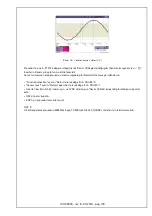
•  İnverteri çalıştırın ve tekrar QS2'yi açın, SENK.'in :“Resim. 12”'teki örneğe uygun olup olmadığını kontrol 
edin;
•  

Tekrar QS2'yi 

Kapatın

;

•  

Prosedür UPS1 için tamam;

NOT:

Bu ofset kompanzasyo

n prosedürü ESB'ye bağlı TÜM üniteler için gerçekleştirilmelidir.

Summary of Contents for 10H92873

Page 1: ...TALLATIONS UND GEBRAUCHSANLEITUNG NOTICE D INSTALLATION ET D UTILISATION ISTRUZIONI DI INSTALLAZIONE E USO INSTRUCCIONES PARA LA INSTALACI N Y EL USO INSTRU ES DE INSTALA O E USO KURMA VE KULLANMA KIL...

Page 2: ...10H92873 rev 8 01 2019 pag 2...

Page 3: ...CTERISTIQUES ELECTRIQUES 50 CARATERISTIQUES MECANIQUES 50 CONFIGURATIONS TYPIQUES 51 INSTALLATION 55 ITALIANO 71 ATTENZIONE 71 DESCRIZIONE 71 CARATTERISTICHE ELETTRICHE 72 CARATTERISTICHE MECCANICHE 7...

Page 4: ...D KKAT 159 TANIMLAMA 159 ELEKTR K ZELL KLER 160 MEKAN K ZELL KLER 160 T P K KONF GURASYONLAR 161 KURMA 165 POLSKI 181 UWAGA 181 OPIS 181 CHARAKTERYSTYKA ELEKTRYCZNA 182 CHARAKTERYSTYKA MECHANICZNA 182...

Page 5: ...S or inside the electrical distribution panel It requires a 230 V input reference supply and can be used to supply two units When installing the unit inside a distribution panel or UPS ensure the meta...

Page 6: ...ont panel UPS sync outputs Min Nominal Max Unit Supply voltage 50 60 Hz sinusoidal 180 230 250 V Supply current 14 mA Output current per channel 25 30 mA Working temperature 10 40 C Phase stability er...

Page 7: ...ts must be chosen as the Master all the other UPS Slave outputs will then follow this reference see Fig 3 for details Fig 3 Two separate mains supplies N B fuses should be installed in the phase signa...

Page 8: ...s synchronized even if one of the two bypass line is out of tolerance More over these units will be normally capable of synchronous operation Fig 4 Common bypass line N B fuses should be connected at...

Page 9: ...d to provide phase reference to Vertiv UPS in installations with alternative power sources such as diesel generators see Fig 5 Fig 5 Vertiv systems and electrical generating devices N B fuses should b...

Page 10: ...ence signal derived from the non Vertiv Master UPS UPS1 and 2 may be configured as parallel or single units see Fig 6 Fig 6 Vertiv and third party brand UPS Installation tips UPS 1 and 2 should be con...

Page 11: ...ync Box in a suitable location protected from harmful environmental conditions such as vibration dust corrosive atmospheres high humidity Install a 2 A slow blow fuse on the phase signal line as close...

Page 12: ...2 PNU 75 21 X_UR2_CRE set to 0 will later be used to calculate the offset PNU 75 22 X_UR3_UV set to 1024 PNU 75 23 X_UR3_IV set to 1024 PNU 75 25 X_UR3_CRE set to 4096 Send all the parameters accordin...

Page 13: ...between inverter and bypass The following figures shows an example of NO SYNC Fig 8 and SYNC Fig 9 Fig 8 Synchro Error 88 56 Fig 9 Synchro Error 88 56 When there is NO SYNC we need to determine the of...

Page 14: ...4 P75 Inv Special Performance Class set the following parameters PNU 51 Access level CU set to Experts Level 3 3 PNU 799 SF Super service set to SF 4 4 PNU 52 Function selection CU set to H W Init URL...

Page 15: ...Super service set to SF 0 0 PNU 51 0 Access level CU set to Normal Operation Level 1 Once back in normal operation open QS1 and the electronics will shut down Follow these steps for ALL the units conn...

Page 16: ...ct synchronisation we will enter a value in PNU 67 1 this is our offset To calculate the offset value PNU 67 1 phase error 65536 360 PNU 67 1 88 56 x 65536 360 PNU 67 1 16121 NOTE If by using this for...

Page 17: ...parameters according to the list above use the send pushbutton Once the parameters are at the Actual Value return to normal operation as follows PNU 52 0 Function selection CU set to Return 0 PNU 799...

Page 18: ...PNU 51 1 Once back in normal operation open QS1 and the electronics will shut down Follow these steps for ALL the units connected to External Synchronisation Box ESB NOTE since the DIC FW Rev 1 10 yo...

Page 19: ...The PNU 700 must be already set to 1 The PNU 731 32 calibration must be done on each UPS composing the system Please perform the following steps Connect your oscilloscope to the first UPS Connect Cha...

Page 20: ...ing calculated the new value for PNU 731 32 please proceed with following steps to change it Close QS2 on this first UPS wait for the Warning W1 1 Bypass Switch Open to be cleared Stop the inverter In...

Page 21: ...10H92873 rev 8 01 2019 pag 17...

Page 22: ...P3700 1 ext synchro enabled P3702 0 P3703 15 P3731 32 0 EXL S1 in the MSS P15700 1 ext synchro enabled TRINERGY CUBE IN EACH CORE P700 1 ext synchro enabled P702 0 P703 15 P731 32 39322 will be used...

Page 23: ...erformed on all UPS of the System Single Distributed Centralised TRINERGY CUBE The offset compensation tuning should be performed on all UPS of the System Single Distributed Centralised PROCEDURE Once...

Page 24: ...When you are satisfied with the result restore the system to Normal Operation as follows Set Function selection to Return PNU 52 0 Set Access level to Normal operation PNU 51 1 Start the inverter ope...

Page 25: ...hronised with a third party brand UPS located in the building basement Each floor is supplied via a CROSS switch Fig 19 Example installation Note the position of the Sync Box this should be selected s...

Page 26: ...10H92873 rev 8 01 2019 pag 22...

Page 27: ...erden zwei Einheiten zu versorgen Wenn die Einheit in eine Verteilertafel oder eine USV installiert wird muss man sicherstellen dass das Met allgeh use so befestigt wird dass es nicht umfallen oder mi...

Page 28: ...ttafel Min Nennwert Max Einheit Versorgungsspannung 50 60 Hz sinusf rmig 180 230 250 V Versorgungsstrom 14 mA Ausgangsstrom pro Kanal 25 30 mA Betriebstemperatur 10 40 C Fehler der Phasenstabilit t 0...

Page 29: ...USVs als Master festgelegt werden und die Ausg nge aller anderen USVs Slaves folgen ihr als Bezug f r genauere Erkl rungen siehe Abb 3 Abb 3 Zwei getrennte Versorgungsnetze ANM An der Leitung des Phas...

Page 30: ...ynchronisiert auch falls eine der beiden Bypassleitungen den Toleranzbereich verl sst Zudem k nnen die Ger te normalerweise synchron Umschalten Abb 4 Zwei Ger te mit gemeinsamer Bypassleitung Hinweis...

Page 31: ...um den Vertiv USVs bei Installationen mit al ternativen Energiequellen wie Dieselgeneratoren einen Phasenbezug zu liefern siehe auch Abb 5 Abb 5 Vertiv Systeme und Stromgeneratoren ANM An der Leitung...

Page 32: ...nicht von Vertiv hergestellt wurde Die USVs 1 und 2 k nnen als Parallelsystem oder als einzelne Einheiten konfiguriert werden siehe auch Abb 6 Abb 6 USVs von Vertiv und von anderen Herstellern Install...

Page 33: ...Sie die Sync Box an einer geeigneten Stelle an wo sie vor sch dlichen Umwelteinfl ssen wie Schwingungen Staub rostbildenden Stoffen und hoher Luftfeuchtigkeit gesch tzt ist Installieren Sie an der Le...

Page 34: ...rechnung verwendet PNU 75 22 X_UR3_UV auf 1024 PNU 75 23 X_UR3_IV auf 1024 PNU 75 25 X_UR3_CRE auf 4096 Senden Sie alle Parameter entsprechend der obigen Liste mithilfe der Senden Taste Schalten Sie w...

Page 35: ...ervenetzes QS2 Pr fen Sie am Oszilloskop den Phasenfehler zwischen dem Wechselrichter und dem Bypass Die nachstehenden Abbildungen zeigen ein Beispiel von KEINE SYNCHRONISATION Abb 8 und SYNCHRO NISAT...

Page 36: ...Parameter Input 14 P75 Inv Special Performance Class die nachstehenden Param eter wie folgt ein PNU 51 Access level CU auf Experts Level 3 3 PNU 799 SF Super service auf SF 4 4 PNU 52 Function select...

Page 37: ...799 0 SF Super service auf SF 0 0 PNU 51 0 Access level CU auf Normal Operation Level 1 ffnen Sie den Schalter QS1 sobald der Normalbetrieb erneut aktiviert wurde die Elektronik schaltet sich aus Geh...

Page 38: ...en im Beispiel von Abb 11 besteht eine Differenz von 88 56 Um eine korrekte Synchronisation zu gew hrleisten muss ein Wert in PNU 67 1 eingegeben werden dies ist der Offset So berechnen Sie den Offset...

Page 39: ...en Normalbetrieb zur ck sobald alle Parameter dem Actual Value entsprechen stellen Sie hierzu die nachstehenden Parameter wie folgt ein PNU 52 0 Function selection CU auf Return 0 PNU 799 0 SF Super s...

Page 40: ...Schalter QS1 sobald der Normalbetrieb erneut aktiviert wurde die Elektronik schaltet sich aus Gehen Sie bei ALLEN Einheiten die an die externe Synchronisationsbox ESB angeschlossen sind wie in dies en...

Page 41: ...ss f r jede USV Einheit durchgef hrt werden die in das System integriert ist Bitte gehen Sie wie folgt vor Schlie en Sie das Oszilloskop an die erste USV Einheit an Schlie en Sie Kanal 1 K1 an Bypass...

Page 42: ...e den Schalter QS2 an der ersten USV Einheit warten Sie bis die Warnung W1 1 Bypass Trennschalter offen gel scht wird Stoppen Sie den Wechselrichter Klicken Sie in PPVis auf Service Tools und w hlen S...

Page 43: ...10H92873 rev 8 01 2019 pag 43...

Page 44: ...er MSS P3700 1 ext Synchro aktiviert P3702 0 P3703 15 P3731 32 0 EXL S1 in der MSS P15700 1 ext Synchro aktiviert TRINERGY CUBE IN JEDEM CORE P700 1 ext Synchro aktiviert P702 0 P703 15 P731 32 39322...

Page 45: ...s Systems Einzel verteilt zentriert durchgef hrt werden TRINERGY CUBE Die Offset Ausgleichseinstellung sollte an allen USV des Systems Einzel verteilt zentriert durchgef hrt werden VORGEHENSWEISE Soba...

Page 46: ...it dem Ergebnis zufrieden sind stellen Sie das System wie folgt wieder auf Normalbetrieb um Setzen Sie Function selection auf Return PNU 52 0 Setzen Sie Access level auf Normal operation PNU 51 1 Star...

Page 47: ...ich wiederum im Keller des Geb udes befindet synchronisiert sind Jedes Stockwerk wird ber einen CROSS Trennschalter versorgt Abb 19 Installationsbeispiel Beachten Sie die Lage der Sync Box sie muss so...

Page 48: ...10H92873 rev 8 01 2019 pag 48...

Page 49: ...l peut tre utilis pour alimenter deux unit s Si l unit est install e l int rieur d un tableau de distribution et d une ASI s assurer que le bo tier m tallique est fix de fa on ne pas se renverser ou e...

Page 50: ...ale 180 230 250 V Courant d alimentation 14 mA Courant la sortie par canal 25 30 mA Temp rature de service 10 40 C Erreur de stabilit de phase 0 18 D placement de phase l int rieur de la plage de tol...

Page 51: ...omme ma tre et les sor ties de toutes les autres ASI esclaves la suivront comme r f rence voir Fig 3 pour plus de d tails Fig 3 Deux r seaux d alimentation s par s Nota Il faut installer des fusibles...

Page 52: ...ours est hors tol rances De plus ces unit s seront normalement capables d effectuer des op rations de transfert synchrones Fig 4 Voie de secours commune Remarque des fusibles doivent tre connect s au...

Page 53: ...f rence de phase aux ASI Vertiv dans les installations avec sources alternatives d nergie comme les g n rateurs Diesel voir Fig 5 Fig 5 Syst mes Vertiv et g n rateurs d nergie lectrique Nota Il faut i...

Page 54: ...ma tre non Vertiv Les ASI 1 et 2 peuvent tre configur es en parall le ou comme unit s ind pendantes voir Fig 6 Fig 6 ASI Vertiv et d autres marques Conseils pour l installation les ASI 1 et 2 doivent...

Page 55: ...s une position appropri e prot g e des conditions ext rieures nocives telles que vibrations poussi re agents atmosph riques corrosifs humidit lev e Installer un fusible retard de 2 A sur la ligne du s...

Page 56: ...Init URL 2 PNU 75 21 X_UR2_CRE r gl sur 0 sera utilis plus tard pour calculer le d calage PNU 75 22 X_UR3_UV r gl sur 1024 PNU 75 23 X_UR3_IV r gl sur 1024 PNU 75 25 X_UR3_CRE r gl sur 4096 Envoyez to...

Page 57: ...r de l entr e de secours QS2 Sur l oscilloscope v rifiez l erreur de phase entre l onduleur et le by pass Les figures suivantes montrent un exemple de NON SYNC Fig 8 et de SYNC Fig 9 Fig 8 Erreur de s...

Page 58: ...effac Arr tez l onduleur Dans PPVis Parameter Input 14 P75 Inv Special Performance Class r glez les param tres suivants PNU 51 Access level CU r gl sur Experts Level 3 3 PNU 799 SF Super service r gl...

Page 59: ...Return 0 PNU 799 0 SF Super service r gl sur SF 0 0 PNU 51 0 Access level CU r gl sur Normal Operation Level 1 Une fois revenu en fonctionnement normal ouvrez QS1 et l lectronique s teindra Suivez ce...

Page 60: ...valeur du d calage PNU 67 1 erreur de phase 65536 360 PNU 67 1 88 56 x 65536 360 PNU 67 1 16121 REMARQUE Si en utilisant cette formule vous ne pouvez pas compenser le d calage essayez la formule suiv...

Page 61: ...res sont sur Actual Value retournez en fonctionnement normal de la mani re suiv ante PNU 52 0 Function selection CU r gl sur Return 0 PNU 799 0 SF Super service r gl sur SF 0 0 PNU 51 0 Access level C...

Page 62: ...U 51 1 Une fois revenu en fonctionnement normal ouvrez QS1 et l lectronique s teindra Suivez ces tapes pour TOUTES les unit s connect es au bo tier de synchronisation externe ESB REMARQUE depuis le FW...

Page 63: ...t d j tre r gl sur 1 Le calibrage PNU 731 32 doit tre effectu sur chaque ASI composant le syst me Veuillez ex cuter les tapes suivantes Connectez votre oscilloscope la premi re ASI Connectez Channel 1...

Page 64: ...PNU 731 32 veuillez suivre la proc dure ci dessous pour entrer les modifications Fermez QS2 sur la premi re ASI attendez que l avertissement W1 1 Bypass Switch Open soit effac Arr tez l onduleur Dans...

Page 65: ...10H92873 rev 8 01 2019 pag 65...

Page 66: ...P3700 1 synchro ext activ e P3702 0 P3703 15 P3731 32 0 EXL S1 dans le MSS P15700 1 synchro ext activ e TRINERGY CUBE DANS CHAQUE C UR P700 1 synchro ext activ e P702 0 P703 15 P731 32 39322 sera uti...

Page 67: ...lis TRINERGY CUBE Le r glage de compensation du d calage doit tre r alis sur toutes les ASI du syst me ind pendant distribu centralis PROC DURE Une fois que ces conditions sont remplies proc dez comme...

Page 68: ...tat est satisfaisant r tablissez le fonctionnement normal du syst me comme suit R glez Function selection sur Return PNU 52 0 R glez Access level sur Normal operation PNU 51 1 D marrez l onduleur ouvr...

Page 69: ...re fabricant situ dans la cave du b timent Chaque niveau est aliment au moyen d un interrupteur CROSS Fig 19 Exemple d installation Observer la position du Sync Box celle ci doit tre s lectionn e de t...

Page 70: ...10H92873 rev 8 01 2019 pag 70...

Page 71: ...ingresso e pu essere utilizzato per alimentare due unit Se l unit viene installata all interno di un quadro di distribuzione o un UPS accertarsi che la scatola metallica sia fissata in modo tale da n...

Page 72: ...usoidale 180 230 250 V Corrente di alimentazione 14 mA Corrente in uscita per canale 25 30 mA Temperatura di esercizio 10 40 C Errore di stabilit di fase 0 18 Spostamento di fase entro la fascia di to...

Page 73: ...come master e le uscite di tutti gli altri UPS slave lo seguiranno come riferimento vedere Fig 3 per maggiori dettagli Fig 3 Due reti di alimentazione separate N B Occorre installare dei fusibili nell...

Page 74: ...ranno normalmente in grado di eseguire operazioni sincronizzate di trasferimento Fig 4 Linea di bypass comune Nota i fusibili dovrebbero essere connessi all inizio della linea di segnale in modo da ev...

Page 75: ...re un riferimento di fase agli UPS Vertiv nelle in stallazioni con sorgenti alternative di energia come generatori diesel vedere Fig 5 Fig 5 Sistemi Vertiv e generatori di energia elettrica N B Occorr...

Page 76: ...nerato dall UPS master non Vertiv Gli UPS 1 e 2 possono essere configurati in parallelo o come unit singole vedere Fig 6 Fig 6 UPS Vertiv e di altre marche Suggerimento per l installazione gli UPS 1 e...

Page 77: ...amenti Collocare il Sync Box in posizione adeguata protetta da condizioni ambientali nocive quali vibrazioni polvere agenti atmosferici corrosivi umidit elevata Installare un fusibile ritardato da 2 A...

Page 78: ...2 PNU 75 21 X_UR2_CRE impostato su 0 in seguito verr utilizzato per calcolare l offset PNU 75 22 X_UR3_UV impostato su 1024 PNU 75 23 X_UR3_IV impostato su 1024 PNU 75 25 X_UR3_CRE impostato su 4096 I...

Page 79: ...gresso di riserva QS2 Verificare sull oscilloscopio l errore di fase tra inverter e bypass Le figure seguenti mostrano un esempio di NO SYNC Fig 8 e SYNC Fig 9 Fig 8 Errore di sincronizzazione 88 56 F...

Page 80: ...Vis Parameter Input 14 P75 Inv Special Performance Class impostare i parametri seguenti PNU 51 Access level CU impostato su Experts Level 3 3 PNU 799 SF Super service impostato su SF 4 4 PNU 52 Functi...

Page 81: ...turn 0 PNU 799 0 SF Super service impostato su SF 0 0 PNU 51 0 Access level CU impostato su Normal Operation Level 1 Dopo il ritorno al funzionamento normale aprire QS1 l elettronica si spegner Attene...

Page 82: ...esto sar l offset Per calcolare il valore di offset PNU 67 1 errore di fase 65536 360 PNU 67 1 88 56 x 65536 360 PNU 67 1 16121 NOTA se tramite questa formula non si riesce a compensare l offset prova...

Page 83: ...opo aver impostato i parametri su Actual Value tornare al funzionamento normale come segue PNU 52 0 Function selection CU impostato su Return 0 PNU 799 0 SF Super service impostato su SF 0 0 PNU 51 0...

Page 84: ...cess level su Normal operation PNU 51 1 Dopo il ritorno al funzionamento normale aprire QS1 l elettronica si spegner Attenersi a questa procedura per TUTTE le unit collegate alla External Synchronisat...

Page 85: ...PNU 700 deve essere gi impostato su 1 La calibrazione PNU 731 32 deve essere eseguita su ogni UPS di cui si compone il sistema Eseguire le operazioni seguenti Collegare l oscilloscopio al primo UPS C...

Page 86: ...U 731 32 procedere con i seguenti step per cambiarlo Chiudere QS2 su questo primo UPS attendere che l avvertenza W1 1 Bypass Switch Open venga cancellata Arrestare l inverter In PPVis fare clic su Ser...

Page 87: ...10H92873 rev 8 01 2019 pag 87...

Page 88: ...zzazione esterna abilitata P3702 0 P3703 15 P3731 32 0 EXL S1 nell MSS P15700 1 sincronizzazione esterna abilitata TRINERGY CUBE IN CIASCUN CORE P700 1 sincronizzazione esterna abilitata P702 0 P703 1...

Page 89: ...UPS del sistema Singolo Distribuito Centralizzato TRINERGY CUBE La regolazione della compensazione dell offset deve essere eseguita su tutti gli UPS del sistema Singolo Distribuito Centralizzato PROCE...

Page 90: ...del risultato ripristinare il Funzionamento normale del sistema come segue impostare Function selection su Return PNU 52 0 impostare Access level su Normal operation PNU 51 1 avviare l inverter aprir...

Page 91: ...oduttore ubicato nello scantinato dell edificio stesso Ogni piano alimentato per mezzo di un interruttore CROSS Fig 19 Esempio di installazione Osservare la posizione del Sync Box questa dev essere se...

Page 92: ...10H92873 rev 8 01 2019 pag 92...

Page 93: ...imentaci n de 230 V y puede ser utilizado para alimentar dos unidades Si instala la unidad en el interior de un cuadro de distribuci n o de un SAI aseg rese de que la caja met lica est fijada de tal m...

Page 94: ...oidal 180 230 250 V Corriente de alimentaci n 14 mA Corriente en salida por canal 25 30 mA Temperatura de ejercicio 10 40 C Error de estabilidad de fase 0 18 Desplazamiento de fase dentro de los l mit...

Page 95: ...AIs como master las salidas de los dem s SAIs slave lo seguir n como referencia v ase Fig 3 para m s detalles Fig 3 Dos redes de alimentaci n separadas NOTA Es necesario instalar los fusibles en la l...

Page 96: ...dos incluso si una de las dos l neas de bypass est fuera de tolerancia Adem s estas unidades son normalmente capaces de operaciones s ncronas de transferencia Fig 4 L nea de bypass com n Nota los fusi...

Page 97: ...referencia de fase a los SAI Vertiv en las in stalaciones con fuentes alternativas de energ a como generadores diesel v ase Fig 5 Fig 5 Sistemas Vertiv y generadores de energ a el ctrica NOTA Es neces...

Page 98: ...gene rada por el SAI master no Vertiv Los SAI 1 y 2 pueden configurarse en paralelo o como unidad nica v ase Fig 6 Fig 6 SAIs Vertiv y de otras marcas Consejos para la instalaci n Los SAI 1 y 2 deben...

Page 99: ...rotegido contra condiciones ambientales nocivas como vibraciones polvo agentes atmosf ricos corrosivos humedad elevada Instale un fusible retardado de 2 A en la l nea de la se al de fase lo m s cerca...

Page 100: ...NU 75 21 X_UR2_CRE ajustar en 0 se usa despu s para calcular el desfase PNU 75 22 X_UR3_UV ajustar en 1024 PNU 75 23 X_UR3_IV ajustar en 1024 PNU 75 25 X_UR3_CRE ajustar en 4096 Enviar todos los par m...

Page 101: ...nterruptor de entrada de reserva QS2 Verificar en el osciloscopio el error de fase entre el inversor y el bypass En las siguientes figuras se muestra un ejemplo de NO SYNC Fig 8 y SYNC Fig 9 Fig 8 Fal...

Page 102: ...Vis Parameter Input 14 P75 Inv Special Performance Class ajustar los siguientes par metros PNU 51 Access level CU ajustar en Experts Level 3 3 PNU 799 SF Super service ajustar en SF 4 4 PNU 52 Functio...

Page 103: ...el CU ajustar en Normal Operation Level 1 Una vez que se se ha vuelto al funcionamiento normal abrir QS1 y la electr nica se apaga Seguir estos pasos en TODAS las unidades conectadas a la ESB 6 4 2 PU...

Page 104: ...U 67 1 error de fase 65536 360 PNU 67 1 88 56 x 65536 360 PNU 67 1 16121 NOTA Si usando esta f rmula no es posible compensar el desfase intentar con la siguiente f rmula PNU 67 1 360 error de fase 655...

Page 105: ...ver al funcionamiento normal de la siguiente manera PNU 52 0 Function selection CU ajustar en Return 0 PNU 799 0 SF Super service ajustar en SF 0 0 PNU 51 0 Access level CU ajustar en Normal Operation...

Page 106: ...l operation PNU 51 1 Una vez que se ha vuelto al funcionamiento normal abrir QS1 y la electr nica se apaga Seguir estos pasos en TODAS las unidades conectadas a la Caja de Sincronizaci n Externa ESB N...

Page 107: ...00 debe estar ya ajustado en 1 La calibraci n PNU 731 32 debe realizarse en cada uno de los SAI que componen el sistema Llevar a cabo los siguientes pasos Conectar el osciloscopio al primer SAI Conect...

Page 108: ...da con los pasos siguientes para cambiarlo Cerrar QS2 en este primer SAI esperar a que se anule la Advertencia W1 1 Conmutador bypass abierto Parar el inversor En PPVis hacer clic en Service Tools y s...

Page 109: ...10H92873 rev 8 01 2019 pag 109...

Page 110: ...cronizaci n externa habilitada P3702 0 P3703 15 P3731 32 0 EXL S1 en el MSS P15700 1 sincronizaci n externa habilitada TRINERGY CUBE EN CADA N CLEO P700 1 sincronizaci n externa habilitada P702 0 P703...

Page 111: ...ibuido centralizado TRINERGY CUBE La puesta a punto de la compensaci n del desfase se deber a realizar en todos los SAI del sistema individual distribuido centralizado PROCEDIMIENTO Una vez que estas...

Page 112: ...n el resultado haga volver al sistema al funcionamiento normal como sigue Establezca Function selection a Return PNU 52 0 Establezca Access level a Normal operation PNU 51 1 Ponga en marcha el inverso...

Page 113: ...de otro productor ubicado en el s tano de dicho edificio Cada piso est alimentado mediante un interruptor CROSS Fig 19 Ejemplo de instalaci n Observe la posici n del Sync Box ste debe seleccionarse d...

Page 114: ...10H92873 rev 8 01 2019 pag 114...

Page 115: ...V em entrada e pode ser utilizado para alimentar duas unidades Se a unidade for instalada dentro de um quadro de distribui o ou num UPS assegure se de que a caixa me t lica esteja fixada de modo tal...

Page 116: ...0 60 Hz sinusoidal 180 230 250 V Corrente de alimenta o 14 mA Corrente em sa da por canal 25 30 mA Temperatura de funcionamento 10 40 C Erro de estabilidade de fase 0 18 Deslocamento de fase dentro da...

Page 117: ...eve ser escolhido como master e as duas sa das de todos os outros UPS slave o seguir o como refer ncia veja Fig 3 para maiores detalhes Fig 3 Duas redes de alimenta o separadas N B preciso instalar os...

Page 118: ...duas linhas de bypass esteja fora dos limites de toler ncia Para al m disso estas unidades ser o geralmente capazes de efectuar opera es de transfer ncia sincronizadas Fig 4 Linha de bypass comum Not...

Page 119: ...do para fornecer uma refer ncia de fase aos UPS Vertiv nas instala es com fontes alternativas de energia como geradores diesel veja Fig 5 Fig 5 Sistemas Vertiv e geradores de energia el ctrica N B pre...

Page 120: ...pelo UPS master n o Vertiv Os UPS 1 e 2 podem ser configurados em paralelo ou como unidade indi vidual veja Fig 6 Fig 6 UPS Vertiv e di altre marche Dicas de instala o o UPS 1 e UPS 2 devem ser confi...

Page 121: ...i o adequada protegido de condi es ambientais nocivas como vibra es p agentes atmosf ricos corrosivos umidade elevada Instale um fus vel atrasado de 2 A na linha do sinal de fase o mais pr ximo poss v...

Page 122: ...do para H W Init URL 2 PNU 75 21 X_UR2_CRE definido para 0 ser mais tarde utilizado para calcular o deslocamento PNU 75 22 X_UR3_UV definido para 1024 PNU 75 23 X_UR3_IV definido para 1024 PNU 75 25 X...

Page 123: ...ptor da entrada de reserva QS2 Verificar no oscilosc pio o erro de fase entre o inversor e o by pass As figuras seguintes mostram um exemplo de SEM SINC Fig 8 e SINC Fig 9 Fig 8 Erro de sincroniza o 8...

Page 124: ...Vis Parameter Input 14 P75 Inv Special Performance Class configurar os seguintes par metros PNU 51 Access level CU definido para Experts Level 3 3 PNU 799 SF Super service definido para SF 4 4 PNU 52...

Page 125: ...n CU definido para Return 0 PNU 799 0 SF Super service definido para SF 0 0 PNU 51 0 Access level CU definido para Normal Operation Level 1 Ap s regressar ao funcionamento normal abrir o QS1 e os comp...

Page 126: ...introduzir um valor no PNU 67 1 este o nosso deslocamento Para calcular o valor do deslocamento PNU 67 1 erro fase 65536 360 PNU 67 1 88 56 x 65536 360 PNU 67 1 16121 NOTA Se utilizando esta f rmula n...

Page 127: ...zar o bot o enviar Depois de introduzir os par metros em Actual Value regressar ao funcionamento normal como se segue PNU 52 0 Function selection CU definido para Return 0 PNU 799 0 SF Super service d...

Page 128: ...Ap s regressar ao funcionamento normal abrir o QS1 e os componentes electr nicos desligam se Seguir estes passos para TODAS as unidades ligadas Caixa de Sincroniza o Externa ESB NOTA desde o DIC FW Re...

Page 129: ...NU 700 j deve estar definido para 1 A calibragem PNU 731 32 deve ser feita em cada UPS que constitui o sistema Realizar os seguintes passos Ligar o seu oscilosc pio ao primeiro UPS Ligar o Channel 1 a...

Page 130: ...lor de PNU 731 32 execute os seguintes passos para o alterar Fechar o QS2 neste primeiro UPS espere pelo Aviso W1 1 Interruptor de by pass aberto desapare a Parar o inversor Em PPVis clicar em Service...

Page 131: ...10H92873 rev 8 01 2019 pag 131...

Page 132: ...MSS P3700 1 sincroniza o ext ativada P3702 0 P3703 15 P3731 32 0 EXL S1 no MSS P15700 1 sincroniza o ext ativada TRINERGY CUBE EM CADA CONDUTOR P700 1 sincroniza o ext ativada P702 0 P703 15 P731 32 3...

Page 133: ...TRINERGY CUBE A afina o de compensa o do desalinhamento deve ser realizada em todas as UPS do sistema simples distribu das e centralizadas PROCEDIMENTO Assim que estas condi es estiverem reunidas proc...

Page 134: ...sfeito com o resultado restaure o sistema para o funcionamento normal como se segue Defina Function selection para Return PNU 52 0 Defina Access level para Normal operation PNU 51 1 Inicie o inversor...

Page 135: ...PS de um outro fabricante posicionado na cantina do edif cio Cada andar alimentado mediante um interruptor CROSS Fig 19 Exemplo de instala o Observe a posi o do Sync Box esta deve ser seleccionada de...

Page 136: ...10H92873 rev 8 01 2019 pag 136...

Page 137: ...PS 2 CROSS Vertiv UPS 80 NET 90 NET Vertiv Vertiv Vertiv UPS 230 V UPS master slave UPS master UPS Vertiv slave slave master slave master slave Multi Bus Vertiv MBSM Multi Bus synchronisation Module 1...

Page 138: ...10H92873 rev 8 01 2019 pag 138 3 4 181 mm 94 mm 64 mm 50 60 Hz 180 230 250 V 14 mA 25 30 mA 10 40 C 0 18 a a 10 1 5 Puc 1 Puc 2 UPS...

Page 139: ...10H92873 rev 8 01 2019 pag 139 5 5 1 UPS UPS master UPS slave Puc 3 Puc 3 UPS master 90 NET XT1 100 200 B...

Page 140: ...10H92873 rev 8 01 2019 pag 140 5 2 Puc 4 90NET B...

Page 141: ...10H92873 rev 8 01 2019 pag 141 5 3 VERTIV UPS Vertiv Puc 5 Puc 5 Vertiv...

Page 142: ...10H92873 rev 8 01 2019 pag 142 5 4 UPS VERTIV UPS Vertiv UPS Vertiv slave UPS master Vertiv UPS 1 2 Puc 6 Puc 6 UPS Vertiv 1 2...

Page 143: ...uc 1 IEC 10 A UPS UPS slave Puc 2 RJ 45 6 2 slave RJ 45 RJ 45 10H54910P15 2 A master master 90 NET UPS L1 N 90 NET B 80 NET 70 NET C 80 NET Black D 80 EXL EXL S1 TRINERGY CUBE 1 10B10877G1 1 2 1 3 RJ...

Page 144: ...2 Function selection CU Return 0 799 SF Super service SF 0 0 51 Access level CU Normal Operation Level 1 PPVis Parameter Input 14 P75 Inv Special Performance Class 51 Access level CU Experts Level 3 3...

Page 145: ...10H92873 rev 8 01 2019 pag 145 Channel 1 Bypass Input L1 N Channel 2 UPS Output L1 N Puc 7 QS2 Puc 8 Puc 9 Puc 8 88 56 Puc 9 0 ESB Main BUS A Reserve input oscilloscope UPS An Fref CH1 CH2 L1 N...

Page 146: ...ass Switch Open PPVis Parameter Input 14 P75 Inv Special Performance Class 51 Access level CU Experts Level 3 3 799 SF Super service SF 4 4 52 Function selection CU H W Init URL 2 75 21 X_UR2_CRE 1612...

Page 147: ...0 Enable External synchronization Yes 1 67 1 VEC_EXT_PHI_OFFSET 0 67 2 VEC_EXT_SYN_F_LIM 1024 67 3 VEC_EXT_SYN_PHI_LIM 1024 67 4 VEC_DELTA_F_GAIN 4096 send Actual Value 52 0 Function selection CU Retu...

Page 148: ...10H92873 rev 8 01 2019 pag 148 QS2 Puc 11 Puc 12 Puc 11 88 56 Puc 12 0 Puc 11 88 56 67 1 67 1 65536 360 67 1 88 56 x 65536 360 67 1 16121 67 1 360 65536 360...

Page 149: ...Inverter Init 51 0 Access level CU Experts Level 3 3 799 0 SF Super service SF 4 4 52 0 Function selection CU H W Init URL 2 67 1 VEC_EXT_PHI_OFFSET 16121 send Actual Value 52 0 Function selection CU...

Page 150: ...Enable 700 1 Function selection Return 52 0 Access level Normal operation 51 1 QS1 ESB External Synchronisation Box DIC FW 1 10 PPVis Service Tools Parameter Parameter set DIC1 Service commissioning 5...

Page 151: ...8 01 2019 pag 151 6 5 2 731 32 ESB ESB 700 1 731 32 Channel 1 Bypass Input L1 N Channel 2 UPS Output L1 N Puc 13 QS2 Puc 14 Puc 15 Puc 14 88 56 ESB Main BUS A Reserve input oscilloscope UPS An Fref C...

Page 152: ...65536 360 731 32 16121 1 731 32 360 65536 360 PNU 731 32 QS2 W1 1 Bypass Switch Open PPVis Service Tools Parameter Access level Superservice 51 4 Function Selection HW Init 52 2 731 32 EXT_SYNCH_OFFSE...

Page 153: ...10H92873 rev 8 01 2019 pag 153...

Page 154: ...1 32 39322 P700 1 P702 0 P703 15 P731 32 39322 80 eXL MSS P3700 1 P3702 0 P3703 15 P3731 32 0 EXL S1 MSS P15700 1 TRINERGY CUBE P700 1 P702 0 P703 15 P731 32 39322 I O BOX P15700 1 RJ45 MBSM 80 eXL X2...

Page 155: ...155 6 6 3 731 32 MBSM MBSM 80 eXL EXL S1 TRINERGY CUBE A Channel 1 Bypass Input L1 N Channel 2 UPS Output L1 N Puc 16 MBSM A NO LOAD QS2 NO SYNC Puc 17 SYNC Puc 18 MBSM Main BUS Reserve input oscillo...

Page 156: ...10H92873 rev 8 01 2019 pag 156 Puc 17 88 56 Puc 18 0 Puc 18 P731 32 Function selection Return PNU 52 0 Access level Normal operation PNU 51 1 QS2 SYNC Puc 18 QS2 1 2 80 eXL EXL S1 COREs MBSM...

Page 157: ...10H92873 rev 8 01 2019 pag 157 6 7 Puc 19 UPS Vertiv UPS CROSS Puc 19 slave 2 A master...

Page 158: ...10H92873 rev 8 01 2019 pag 158...

Page 159: ...talik bir kutuya yerle tirilmi tir Giri te 230 V l k bir beslemeye ihtiya duyar ve iki nit eyide besleyebilir E er nite bir da t m tablosu i ine veya bir UPS i ine kurulacaksa metalik kutunun devrilme...

Page 160: ...ite Besleme gerilimi 50 60 Hz sinusoidale 180 230 250 V Besleme ak m 14 mA k taki ak m kanal i in 25 30 mA Alet s s 10 40 C Sabit faz hatas 0 18 Giri teki gerilim tolerans dilimi faz n n yer de i tirm...

Page 161: ...se ilmelidir ve di er t m UPS lerin slave k lar referans olarak onu takip edeceklerdir bak n z Resim 3 daha fazla bilgi i in Resim 3 Ayr besleme a lar N B Muhtemel k sa devre neticesinde olu abilecek...

Page 162: ...iki sistem her zaman senkronize olacakt r Ayr ca bu niteler normal olarak senkronize aktarma i lemini de ger ekle tirebileceklerdir Resim 4 Ortak bypass hatt ile iki ekipman Not sigortalar kablolarda...

Page 163: ...kaynaklar dizel jenara r gibi ile birlikte UPS Vertiv in yerle tirilmesinde bir referans faz olarak kullan labilir Resim 5 Resim 5 Vertiv sistemleri ve elektrik enerjisi jenerat rleri N B Muhtemel k...

Page 164: ...den de il ama UPS master den gelen referans faz n takip etmek m mk n olur 1 ve 2 UPS ler paralel veya tek olarak konfigure edilebilirler bak n z Resim 6 Resim 6 UPS Vertiv ve di er markalar Kurma tavs...

Page 165: ...kullanmay n z Sync Box u uygun bir pozisyonda ba lay n z zarar verebilecek evre ko ullar ndan koruyunuz bunlar titre imler toz bozabilecek atmosferik durumlar y ksek nem oran Master nitesine m mk n ol...

Page 166: ...ection CU esini H W Init URL 2 olarak ayarlay n PNU 75 21 X_UR2_CRE esi 0 olarak ayarl daha sonra ofseti hesaplamak i in kullan lacakt r PNU 75 22 X_UR3_UV esi 1024 olarak ayarl PNU 75 23 X_UR3_IV esi...

Page 167: ...yedek giri alterini a n Osiloskopta inverter ile baypas aras ndaki faz hatas n onaylay n A a daki ekillerde SENK YOK Resim 8 ve SENK Resim 9 rne i verilmi tir Resim 8 Senkro Hatasi 88 56 Resim 9 Senk...

Page 168: ...rmance Class esinde u parametreleri ayarlay n PNU 51 Access level CU esini Experts Level 3 3 olarak ayarlay n PNU 799 SF S per servis esini SF 4 4 olarak ayarlay n PNU 52 Function selection CU esini H...

Page 169: ...CU esini Return 0 olarak ayarlay n PNU 799 0 SF Super service esini SF 0 0 olarak ayarlay n PNU 51 0 Access level CU esini Normal Operation Level 1 olarak ayarlay n Normal al maya d n ld nde a k QS1 v...

Page 170: ...ofsettir Ofset de erini hesaplamak i in PNU 67 1 faz hatas 65536 360 PNU 67 1 88 56 x 65536 360 PNU 67 1 16121 NOT Bu form l kullanarak ofseti kompanse edemiyorsan z u form l deneyin PNU 67 1 360 faz...

Page 171: ...kullan n Parametreler Ger ek De er seviyesine geldi inde u ekilde normal al maya d n n PNU 52 0 Function selection CU esini Return 0 olarak ayarlay n PNU 799 0 SF Super service esini SF 0 0 olarak aya...

Page 172: ...lay n PNU 51 1 Normal al maya d n ld nde a k QS1 ve elektronik donan m kapanacakt r Bu i lemleri Harici Senkronizasyon Kutusu na ESB ba l T M niteler i in ger ekle tirin NOT DIC FW Rev 1 10 dan itibar...

Page 173: ...700 ise 1 olarak ayarlanm olmal d r PNU 731 32 kalibrasyonu sistemi olu turan her bir UPS de yap lmal d r L tfen u i lemleri ger ekle tirin Osiloskopu ilk UPS ye ba lay n Channel 1 esini Bypass Input...

Page 174: ...gulay n Bu ilk UPS de QS2 yi Kapat n Uyar W1 1 Baypas alteri A k uyar s n n silinmesini bekleyin nverteri durdurun PPVis de Service Tools esini t klat n ve Parameter esini se in Access level esini Sup...

Page 175: ...10H92873 rev 8 01 2019 pag 175...

Page 176: ...ile MSS P3700 1 d senkro etkin P3702 0 P3703 15 P3731 32 0 EXL S1 ile MSS P15700 1 d senkro etkin TRINERGY CUBE HER B R G MOD L N P700 1 d senkro etkin P702 0 P703 15 P731 32 39322 sonradan ofset ayar...

Page 177: ...rkezi TRINERGY CUBE Ofset dengeleme ayar Sistemin t m KGK lerinde yap lmal d r Tek Da t lm Merkezi PROSED R Bu ko ullar sa land ktan sonra u i lemleri takip edin Osiloskopu ilk KGK ya ba lay n ift ver...

Page 178: ...a sistemi a a daki gibi Normal al maya geri d nd r n Function selection ayar n Return olarak de i itirin PNU 52 0 Access level ayar n Normal operation olarak de i itirin PNU 51 1 nverteri ba lat n QS2...

Page 179: ...bulunan bir ba ka reticinin UPS i ile senkrasyon da olsun Her kat bir CROSS elektrik d mesi ile beslenir Resim 19 Kurma rne i Sync Box un pozisyonunu dikkatle g zleyin bu yle bir se ilmelidirki slave...

Page 180: ...10H92873 rev 8 01 2019 pag 180...

Page 181: ...referencyjnego pr dem o napi ciu 230 V i mo na go u ywa do zasilania dw ch urz dze Podczas instalacji urz dzenia wewn trz panelu dystrybucji lub na urz dzeniu UPS nale y si upewni e met alowa obudowa...

Page 182: ...chronizacji Min Nominal Max Unit Napi cie zasilania 50 60 Hz sinusoidalne 180 230 250 V Pr d zasilania 14 mA Pr d wyj ciowy dla ka dego kana u 25 30 mA Temperatura pracy 10 40 C B d stabilno ci fazy 0...

Page 183: ...wyj cia skonfigurowane jako slave b d w wczas ledzi t referencj i dostosowywa si do niej szczeg y na ilustracja 3 ilustracja 3 Dwa oddzielne r d a zasilania UWAGA Bezpieczniki topikowy nale y zainsta...

Page 184: ...ej ciowych znajdzie si poza zakresem tolerancji Co wi cej zespo y te b d normalnie zdolne do wykonywania operacji przenoszenia synchronicznego ilustracja 4 Dwa urz dzenia ze wsp ln lini obej ciow Uwag...

Page 185: ...dla urz dze UPS firmy Ver tiv w instalacjach zasilanych z alternatywnych r de zasilania takich jak generatory diesel patrz ilustracja 5 ilustracja 5 Systemy Vertiv i generatory energii elektrycznej U...

Page 186: ...aster innej marki Jednostki UPS 1 i 2 mog by skonfig urowane jako po czone r wnolegle lub jako pojedyncze urz dzenia patrz ilustracja 6 ilustracja 6 UPS firmyVertiv i innych marek Wskaz wki instalacyj...

Page 187: ...c Box w odpowiednim miejscu tak aby by chroniony przed szkodliwymi czynnikami rodowiskowymi takimi jak Wibracje py czynniki powoduj ce korozj du a wilgotno Zainstalowa bezpiecznik topikowy zw oczny na...

Page 188: ...X_UR2_CRE ustaw na 0 zostanie u yte p niej do obliczenia przesuni cia PNU 75 22 X_UR3_UV ustaw na 1024 PNU 75 23 X_UR3_IV ustaw na 1024 PNU 75 25 X_UR3_CRE ustaw na 4096 Wy lij wszystkie parametry zg...

Page 189: ...ikiem i obej ciem Na poni szych rysunkach pokazano przyk ad BRAKU SYNCHRONIZACJI ilustracja 8 i SYNCHRONIZACJI il ustracja 9 ilustracja 8 B d synchronizacji 88 56 ilustracja 9 B d synchronizacji 0 Gdy...

Page 190: ...Class ustaw nast puj ce parametry PNU 51 Access level CU ustaw na Experts Level 3 3 PNU 799 SF Super service ustaw na SF 4 4 PNU 52 Function selection CU ustaw na H W Init URL 2 PNU 75 21 X_UR2_CRE us...

Page 191: ...y spos b PNU 52 0 Function selection CU ustaw na Return 0 PNU 799 0 SF Super service ustaw na SF 0 0 PNU 510 Access level CU ustaw na Normal Operation Level 1 Po przywr ceniu normalnego dzia ania otw...

Page 192: ...dzi BRAK SYNCHRONIZACJI nale y okre li przesuni cie pomi dzy dwoma kszta tami fali na przyk adzie z ilustracja 11 wyst puje r nica 88 56 W celu zapewnienia prawid owej synchronizacji nale y wprowadzi...

Page 193: ...adzie 16121 Wy lij wszystkie parametry zgodnie z powy sz list u yj przycisku wysy ania Po osi gni ciu przez wszystkie parametry Actual Value wr do normalnej pracy w nast puj cy spos b PNU 52 0 Functio...

Page 194: ...malnego dzia ania otw rz QS1 i elektronika zostanie wy czona Wykonaj te czynno ci na WSZYSTKICH zespo ach pod czonych do skrzynki zewn trznej synchronizacji ang External Synchronisation Box ESB UWAGA...

Page 195: ...adowany i ustawiony na 1 Kalibracja PNU 731 32 musi by przeprowadzona dla ka dego UPS sk adaj cego si na system Wykonaj nast puj ce kroki Pod cz oscyloskop do pierwszego UPS Pod cz Channel 1 do Bypass...

Page 196: ...parametru PNU 731 32 wykonaj poni sze kroki aby zmieni parametr Zamknij QS2 na pierwszym UPS odczekaj na skasowanie Ostrze enia W1 1 Otwarty prze cznik obej ciowy Zatrzymaj falownik W PPVis kliknij Se...

Page 197: ...10H92873 rev 8 01 2019 pag 197...

Page 198: ...S P3700 1 zewn synchronizacja w czona P3702 0 P3703 15 P3731 32 0 EXL S1 w MSS P15700 1 zewn synchronizacja w czona TRINERGY CUBE W KA DYM RDZENIU P700 1 zewn synchronizacja w czona P702 0 P703 15 P73...

Page 199: ...sacji odchy ki nale y przeprowadzi na wszystkich zasilaczach UPS w systemie konfiguracja pojedyncza rozproszona zcentralizowana PROCEDURA Po spe nieniu wymienionych wymog w nale y post powa w nast puj...

Page 200: ...przywr ci normalne dzia anie systemu Ustaw opcj Function selection na Return PNU 52 0 Ustaw opcj Access level na Normal operation PNU 51 1 Uruchom falownik ponownie otw rz prze cznik QS2 a nast pnie s...

Page 201: ...onizowanych z inn mark urz dze UPS zainstalowanych w podziemiach budynku Ka de pi tro jest zasilane poprzez prze cznik CROSS ilustracja 19 Przyk adowa instalacja Prosz zwr ci uwag na pozycj modu u Syn...

Page 202: ...10H92873 rev 8 01 2019 pag 202...

Reviews: