System Application Guide
SAG582136800
Spec. No. 582136800 (Model 502
NGFB
)
Revision BA, April 8, 2020
Page 19 of 129
♦
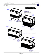
Termination panel includes AC input and DC output Bus bars.
♦
System houses up to five (5) Rectifier Modules and one (1) Controller.
♦
A screw-type terminal block is provided for connection of a battery and a load remote shunt.
Restrictions
System is non-expandable.
Ordering Notes
1)
Order List 7 as required. Also order the following as required.
2)
Order up to five (5) Rectifier Modules (P/N
) per system.
3)
Order one (1) optional Rectifier Module Mounting Position Blank Cover Panel (P/N PSK4830R-1) for each empty rectifier
module mounting position in the system if required.
4)
) Controller per system. Also specify appropriate configuration file for your site.
5)
Order IB2 Interface Board Assembly, (P/N
) as required.
6)
Order up to two (2) Temperature Probes (
) as required. See “Optional Temperature Probes” on page 68 for
temperature probe options with a mounting tab.
7)
Order Relay Rack Anchor Kit(s) (
) as required.
8)
Order
section.
9)
Order
AC Input Cables and Line Cords
section.
10)
Order
section.
11)
Order output lugs per
section.
List 8: 23” Assembled System with One (1) Main Shelf, One (1) Expansion Shelf,
and AC Input / Bulk DC Output Termination Panel
Features
♦
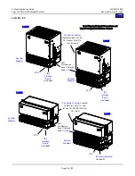
Consists of two (2) 2RU high by 23” wide rectifier shelves and one (1) 2RU high by 23” termination panel (pre-assembled
for 6RU total).
♦
Termination panel includes AC input and DC output Bus bars.
♦
System houses up to eleven (11) Rectifier Modules and one (1) Controller.
♦
A screw-type terminal block is provided for connection of a battery and a load remote shunt.
Restrictions
System is non-expandable.
Ordering Notes
1)
Order List 8 as required. Also order the following as required.
2)
Order up to eleven (11) Rectifier Modules (P/N
) per system.
3)
Order one (1) optional Rectifier Module Mounting Position Blank Cover Panel (P/N PSK4830R-1) for each empty rectifier
module mounting position in the system if required.
4)
) Controller per system. Also specify appropriate configuration file for your site.
5)
Order IB2 Interface Board Assembly, (P/N
) as required.
6)
Order up to two (2) Temperature Probes (
) as required. See “Optional Temperature Probes” on page 68 for
temperature probe options with a mounting tab.
7)
Order Relay Rack Anchor Kit(s) (
) as required.
8)
Order
section.
9)
Order
AC Input Cables and Line Cords
section.
10)
Order
section.
11)
Order output lugs per
section.

