System Application Guide
SAG582136800
Spec. No. 582136800 (Model 502
NGFB
)
Revision BA, April 8, 2020
Page 89 of 129
Wiring Notes
Refer also to the next section,
AC Input Connections
Features
♦
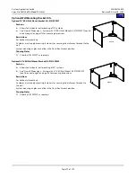
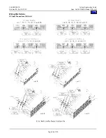
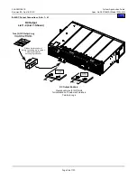
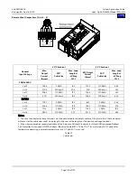
Each system contains multiple plug-in AC input connectors. For details, refer to the illustration provided in the
♦
AC input branch circuits are connected via AC Input Cable Assemblies/Line Cords ordered with the system.
Restrictions
For correct AC input wire size, order AC Input Cable Assembly or Line Cords per the ACCESSORY DESCRIPTIONS section.
Each system requires multiple AC input branch circuits. Each AC input branch circuit feeds one (1) or (2) rectifiers.
Recommended branch circuit protection is 30 amperes.
Branch circuit protective devices should be of the time-delay or high inrush type.
DC Output Connections
Features
♦
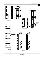
Lists 1 – 4: Bus bars with 3/8” clearance holes on 1" centers are provided for installation of customer-furnished DC
output cables terminated in two-hole lugs.
♦
Lists 5 – 8: 3/8-16 studs on 1" centers are provided for installation of customer-furnished DC output cables terminated in
two-hole lugs.
♦
Lists 10 – 13 and 16 – 27: Distribution Cabinets provide 1/4-20 studs on 5/8” centers for installation of customer-
furnished DC Load and Load Return distribution cables terminated in two-hole lugs.
♦
Lists 14 – 15: These field expansion shelves are furnished with output busbars for connection to existing power system
buswork.
♦
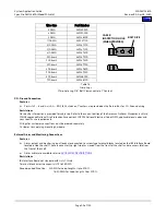
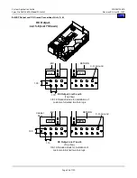
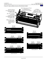
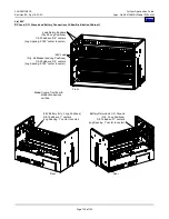
For lug landing details, refer to the illustration provided in the
Restrictions
List 1 – 4: Customer wiring must connect the DC outputs of the main shelf and all expansion shelves in a system in parallel.
When connecting the outputs of multiple shelves, the wiring from all shelves should be of the same gauge and similar length.
Ordering Notes
1)
All lugs for customer connections must be ordered separately. Customer to supply lug mounting hardware.
2)
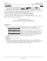
The rating of the distribution device determines the wire size requirements. For wire size and lug selection, refer to the
following:
•
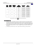
Lists 1 – 8: Tables 14A – 14E
•
Lists 10 – 13 and 16 – 27: Table 15
3)
For other available lugs and hardware, refer to drawings 031110100 through 031110300.

