SAG582136800
System Application Guide
Revision BA, April 8, 2020
Spec. No. 582136800 (Model 502
NGFB
)
Page 94 of 129
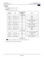
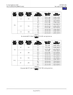
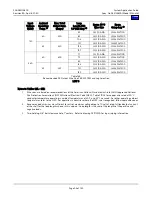
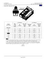
Notes to Table 15:
1
Wire sizes are based on recommendations of the American National Standards Institute (ANSI) approved National
Fire Protection Association's (NFPA) National Electrical Code (NEC). Table 310-16 for wire rated at 90
°
C conductor
temperature operating in ambient temperatures of 40
°
C, 50°C, and 65°C was used. For other operating ambient
temperatures, refer to the NEC. For operation in countries where the NEC is not recognized, follow applicable codes.
2
Recommended wire sizes are sufficient to restrict voltage drop to 1.0 volt or less at listed branch current for the loop lengths
shown. Loop length is the sum of the lengths of the positive and negative leads.
3
Wire Size / Loop Length Combination Calculated using 40°C Ambient Operating Temperature.
4
Wire Size / Loop Length Combination Calculated using 50°C Ambient Operating Temperature.
5
Wire Size / Loop Length Combination Calculated using 65°C Ambient Operating Temperature.
6
These lugs are two-hole for 1/4" bolt clearance on 5/8" centers. Refer to drawing 031110100 for lug crimping information.
7
Special application crimp lug / strap combination.
Table 15 (cont’d from previous page)
Recommended Distribution (Load) Wire Size and Lug Selection for
TLS/TPS Fuse and Bullet Nose-Type Circuit Breaker (Load and Load Return)
Battery Connections
Features
♦
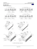
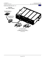
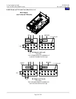
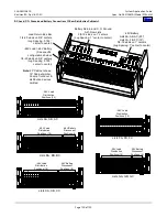
In each Distribution Cabinet, lug-terminated battery conductors are connected to the battery terminals as follows: Each
Distribution Cabinet provides the following connection points for two-hole lug-terminated battery wires:
•
Lists AA, AB, AC, FA, FB, FC and MV: Battery and Battery Return busbars provide 3/8” threaded studs on 1”
centers.
•
All Other 1-Row Distribution Cabinets: Battery disconnect positions provide 1/4“ threaded studs on 5/8” centers.
Return connections can be made to Battery Return busbar, which provides 3/8” threaded studs on 1” centers.
Return connections can also be made to Load Return busbar, which provides 1/4“ threaded studs on 5/8” centers.
•
All Other 2-Row Distribution Cabinets: Battery disconnect positions provide 1/4“ threaded studs on 5/8” centers.
Return connections are made to Load Return busbar, which provides 1/4“ threaded studs on 5/8” centers.
♦
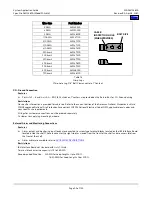
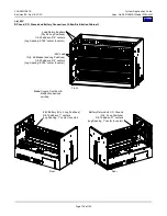
For lug landing details, refer to the illustration provided in the
Restrictions
Customer must supply lug-mounting hardware
.
Ordering Notes
1)
Battery wire size varies depending on battery capacity; therefore no specific information is provided for wire size.
2)
All lugs for customer connections must be ordered separately. For available lugs for Lists AA, AB, AC, FA, FB, FC and MV,
refer to
. For available lugs for all other 1-Row Distribution Cabinets and for all other 2-Row Distribution
Cabinets, refer to
. Refer to drawing 031110100 for lug crimping information.


