Vertiv™ NetSure™ 512
NGBB
-48 VDC Power System User Manual
Proprietary and Confidential © 2022 Vertiv Group Corp.
8
ALERT!
The system can either have +24V DC-DC converters installed or -58V DC-DC converters installed. The system
cannot have both types of converters installed at the same time.
ALERT!
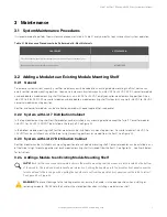
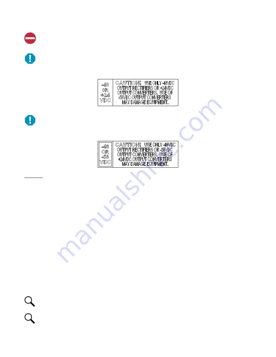
The -48 VDC to +24 VDC converter modules must only be installed in a system position that accepts a +24V DC-DC
converter. Refer to labeling on the system’s module mounting shelf. A sample of this labeling is provided in Figure 3.1.
Figure 3.1 Sample Module Mounting Shelf Labeling
ALERT!
The -48 VDC to -58 VDC converter modules must only be installed in a system position that accepts a -58V DC-DC
converter. Refer to labeling on the system’s module mounting shelf. A sample of this labeling is provided in Figure 3.2.
Figure 3.2 Sample Module Mounting Shelf Labeling
Procedure
1.
Unpack the modules.
2.
Note the model number located on the front of each module. Model numbers starting with the letter “R” are rectifier modules.
Model numbers starting with the letter “C” are converter modules.
3.
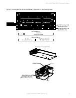
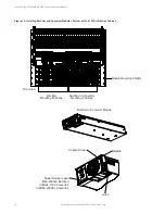
Place the module into an unoccupied mounting position without sliding it in completely. See Figure 3.3 or Figure 3.4 for
acceptable positions. Each module mounting assembly may house rectifier modules, optional -48 VDC to +24 VDC converter
modules, or optional -48 VDC to -58 VDC converter modules (depending on configuration).
4.
Loosen the captive screw on the module’s handle. Pull the handle down out from the module’s front panel (this will also
retract the latch mechanism). See Figure 3.3 or Figure 3.4.
5.
Push the module completely into the shelf.
6.
Push the handle up into the module’s front panel. This will lock the module securely to the shelf. Tighten the captive screw
on the handle.
7.
Repeat the above steps for each module being installed in the system.
8.
After the modules are physically installed in the mounting shelf(s), they are ready for operation immediately after power is
supplied to them.
NOTE!
It is recommended that the current limit point be checked whenever a rectifier is added to or removed from the
power system. Refer to “Checking the Controller’s Current Limit Point after Adding or Removing a Rectifier.”
NOTE!
The rectifier or converter being added is assigned by the controller the lowest available identification number. If
desired, you can change the identification number. Refer to the NCU Instructions (UM1M830BNA) for a procedure.


