Vertiv™ NetSure™ 512
NGBB
-48 VDC Power System User Manual
Proprietary and Confidential © 2022 Vertiv Group Corp.
12
8.
Re-install the rear busbar shield previously removed from the existing module mounting shelf. Re-install the rear busbar
shield previously removed from the expansion module mounting shelf.
9.
Refer to the Power System Installation Instructions (IM582137000) and connect AC input power to the expansion module
mounting shelf.
10.
Refer to the Power System Installation Instructions (IM582137000) and install rectifier and converter modules into the
expansion module mounting shelf as required.
11.
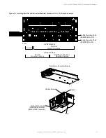
For the expansion shelf, two sets of converter polarity caution labels are provided loose. Based on the converter output
voltage, apply the correct label to right three converter slots of the expansion shelf: “-48 VDC OR +24 VDC” label (P/N
60037065) for use with +24 VDC converters; “-48 VDC OR -58 VDC” label (P/N 60037064) for use with -58 VDC converters.
A sample of this labeling is provided in Figure 3.5.
Figure 3.5 Caution Labels
60037065 (-48VDC OR +24VDC Label)
60037064 (-48VDC OR -58VDC Label)


