Vertiv™ NetSure™ 512
NGBB
-48 VDC Power System User Manual
Proprietary and Confidential © 2022 Vertiv Group Corp.
13
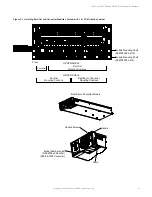
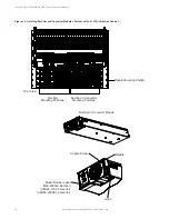
Figure 3.6 Installing a Field Expansion Module Mounting Shelf in a System with List 27 Distribution Cabinet
1. Remove busbar rear shield from
lowest module mounting shelf
in rack. Remove the bottom panel
from the busbar rear shield.
a. Remove the mounting angles
attached to the shelf and
replace with P/N 60056566.
Place the mounting angle
in position as shown below.
2. Remove hardware from the
3. Install the expansion module
mounting shelf into the rack.
4. Remove busbar rear shield from
expansion module mounting shelf.
5. Install the busbars provided
with the expansion module
mounting shelf between the
shelves. Torque to 60 in-lbs.
6. Re-install the rear busbar
shields previously removed.
Rear
Front
Rear
Busbar Rear Shield
Apply “-48 VDC OR -58 VDC” label or
“-48 VDC OR +24 VDC” label to right
three converter slots of the expansion shelf
based on the converter output voltage.
lowest module mounting
-48V, return, and +24V or -58V
(if present) busbars.
shelf’s


