Vertiv™ NetSure™ 5100 Series -48 VDC Power System User Manual
Proprietary and Confidential © 2022 Vertiv Group Corp.
6
3.5
Controller Battery Charge Current Limit Feature
Functionality: After a failure of the input source (commercial AC or DC) or when some battery cells are permanently damaged, the
current to the batteries can be quite extensive. To avoid overheating or further damages to the battery, the controller can be
programmed to limit the battery current to a preset level by limiting the charging voltage of the rectifiers and solar converters. Should
the battery current still exceed a higher preset value, an alarm is issued.
The controller limits the current going to the batteries based on the “Battery Current Limit” set point which is a percentage of the
battery capacity in C10. For example, 0.1C10 would mean 10% of the battery capacity. If the C10 capacity of a battery is 100 amp-hr,
the battery recharge current limiting setpoint is 0.1C10; therefore, the recharge current is limited to 10 A.
Refer to the NCU Controller Instructions (UM1M830BNA) to program this feature. Battery charge current is limited to the value set in
the controller, as long as battery voltage is above 47 VDC.
3.6
Local Controls and Indicators
General
Refer to the Controller, Rectifier, Solar Converter, -48 VDC to +24 VDC Converter, or -48 VDC to -58 VDC Converter, Inverter
Instructions for descriptions of the local controls and indicators located on these units.
Optional Critical Alarm Indicator
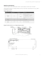
The system may be equipped with an optional critical alarm indicator which illuminates if the NCU controller issues a critical alarm.
Refer to Figure 3.1.
List KG GMT Load Distribution Fuse Panel
Refer to Figure 3.2 for indicator locations.
PWR A and PWR B Indicators:
These indicators illuminate (green) to indicate power is supplied to the A and B sides of the panel,
respectively.
NOTE!
The split (A/B) input bus option provided on this panel is strapped for a single input in this power system.
FUSE ALARM Indicator:
This indicator illuminates (red) to indicate a load distribution fuse is open. The open fuse also provides a
mechanical indicator visible through the fuse safety cover.
Optional Transient Voltage Surge Suppressor (TVSS) Device
An optional Transient Voltage Surge Suppressor (TVSS) device contains an indicator which illuminates when the circuit activates to
suppress voltages. See Figure 3.3.


