Vertiv™ NetSure™ 5100 Series -48 VDC Power System User Manual
Proprietary and Confidential © 2022 Vertiv Group Corp.
13
ALERT!
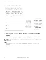
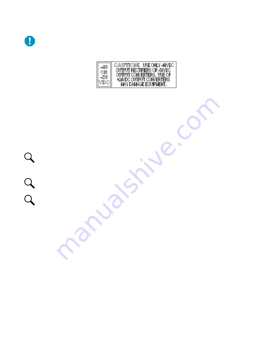
The -48 VDC to -58 VDC converter modules must only be installed in a system position that accepts a -58V DC-DC
converter. Refer to labeling on the system’s module mounting shelf. A sample of this labeling is provided in Figure 4.2.
Figure 4.2 Sample Module Mounting Shelf Labeling
1.
Unpack the modules.
2.
Note the model number located on the front of each module. Model numbers starting with the letter “R” are rectifier modules.
Model numbers starting with the letter “C” are converter modules. Model numbers starting with the letter “S” are solar
converter modules.
3.
Place the module into an unoccupied mounting position without sliding it in completely. Each module mounting assembly
may house rectifier modules, optional solar converter modules, optional -48 VDC to +24 VDC converter modules, optional
-48 VDC to -58 VDC converter modules, and a controller (depending on configuration).
NOTE!
Refer to the module position identification label located either on the inside of the distribution cabinet door (rack
mounted systems) or inside the OSP cabinet when no door is furnished for acceptable rectifier, solar converter, and -48 VDC
to +24 VDC converter or -48 VDC to -58 VDC converter module mounting positions in the specific module mounting
assembly(s) contained in your system. See Figure 4.6.
NOTE!
See PD588705300 for additional acceptable module position details.
NOTE!
For systems using an AC feed option where each feed connects to two (2) slots in the shelf (List 46 or Molex
connected cords) and -48 VDC to +24 VDC converters or -48 VDC to -58 VDC converters are being used (List 26 two row
distribution panel or List 27 single row distribution panel) in the plant, the following module restrictions apply for factory
installed shelves 2 through 5:
o
Rectifiers can be in any or all six (6) positions if three (3) AC inputs provided.
o
+24V or -58V converters can be in the right three (3) positions (positions 4, 5 and 6).
o
Rectifiers can be in any position which has AC power that is not taken up with a converter.
o
One (1) Solar converter can be installed in the shelf, position 1 or 2.
o
Three (3) solar converters can be installed in the shelf, positions 1 or 2, positions 3 or 4 and positions 5 or 6 if the -48V
to +24V or -48V to -58V bus bar is not installed to the shelf above.
4.
Loosen the captive screw on the module’s handle. Pull the handle down out from the module’s front panel (this will also
retract the latch mechanism). See Figure 4.3, Figure 4.4, or Figure 4.5.
5.
Push the module completely into the module mounting assembly.
6.
Push the handle up into the module’s front panel. This will lock the module securely to the module mounting assembly.
Tighten the captive screw on the handle.
7.
Repeat the above steps for each module being installed in the system.


