Vertiv™ NetSure™ 5100 Series -48 VDC Power System User Manual
Proprietary and Confidential © 2022 Vertiv Group Corp.
18
7.
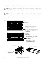
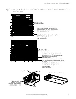
Disconnect the CAN cable coming from the distribution cabinet from the connector on the bottom-most existing module
mounting assembly and connect this cable to the same connector on the expansion module mounting assembly.
8.
Connect the open CAN connector on the bottom-most existing module mounting assembly to the open connector on the
expansion module mounting assembly.
9.
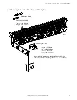
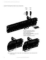
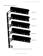
Re-install the rear busbar shield previously removed from the existing module mounting assembly. Re-install the rear busbar
shield previously removed from the expansion module mounting assembly.
10.
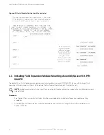
As an expansion shelf is installed, adhere the label furnished with the shelf to the bottom open shelf position on the label
shown in Figure 4.10. This label is located either on the inside of the distribution cabinet door (rack mounted systems) or
inside the OSP cabinet when no door is furnished.
11.
Refer to the Power System Installation Instructions (IM582137100) and connect input power to the expansion module
mounting assembly.
NOTE!
The List 36 expansion shelf has a Molex input feed where each feed connects to two (2) slots in the shelf. The
following module restrictions apply:
o
Rectifiers can be in any or all six (6) positions if three (3) AC inputs provided.
o
+24V or -58V converters can be in the right three (3) positions (positions 4, 5 and 6).
o
Rectifiers can be in any position which has AC power that is not taken up with a converter.
o
One (1) Solar converter can be installed in the shelf, position 1 or 2.
o
Three (3) solar converters can be installed in the shelf, positions 1 or 2, positions 3 or 4 and positions 5 or 6 if the -48V
to +24V or -48V to -58V bus bar is not installed to the shelf above.
NOTE!
Locate the module position identification label either on the inside of the distribution cabinet door (rack mounted
systems) or inside the OSP cabinet when no door is furnished. As the shelf is being wired for module inputs, write the type of
module to be placed in each module mounting position in the space provided on the label. Write R for rectifier, C for
converter, and S for solar converter. See Figure 4.6.
12.
Refer to the Power System Installation Instructions (IM582137100) and install rectifier, solar converter, -48 VDC to
+24 VDC converter and/or -48 VDC to -58 VDC converter modules into the expansion module mounting assembly as
required.
NOTE!
Refer to the module position identification label located either on the inside of the distribution cabinet door (rack
mounted systems) or inside the OSP cabinet when no door is furnished for acceptable rectifier, solar converter, -48 VDC to
+24 VDC converter and -48 VDC to -58 VDC converter module mounting positions in the specific module mounting
assembly(s) contained in your system. See Figure 4.6.
NOTE!
See PD588705300 for additional acceptable module position details and the NOTE in step 11.
NOTE!
When installing in a data cabinet, refer also to “Installing Field Expansion Module Mounting Assembly Spacer Kit, P/N


