background image

Vertiv™ NetSure™ 5100 Series -48 VDC Power System User Manual 

Proprietary and Confidential © 2022 Vertiv Group Corp. 

72 

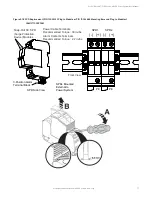
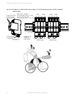
Figure 5.19  SPD Replacement (P/N 10035033 Plug-In Module or P/N 10034885 Mounting Base and Plug-In Modules) 

(582137100500) 


Power Cable Terminals

Recommended Torque:  30 in-lbs.
Alarm Contacts Terminals

Recommended Torque:  2.2 in-lbs.

SPDs Mounted

External to

Power System

Front View

-48VDC/Return

-58VDC/Return

SPD1

SPD2

SPD3

SPD4

(-)   (+) (-)   (+)

(-)   (+) (-)   (+)

PE

PE

PE

PE

SPD Side View

Snap-Out DC SPD

(Surge Protection

Device) Modules

3-Position Alarm

Terminal Block

Summary of Contents for 582137100

Page 1: ...NetSure 5100 Series 48 VDC Power System User Manual Specification Number 582137100 Model Number 5100 ...

Page 2: ...dures not specifically described in this document The products covered by this instruction manual are manufactured and or sold by Vertiv This document is the property of Vertiv and contains confidential and proprietary information owned by Vertiv Any copying use or disclosure of it without the written permission of Vertiv is strictly prohibited Names of companies and products are trademarks or reg...

Page 3: ...e to an Existing Inverter Module Mounting Assembly 24 4 6 Reconfiguring a Dual Voltage Distribution Panel List DA DB DC DD DE FA FB FC FD FE 26 4 7 Reconfiguring the Distribution Voltage on Positions 23 to 26 of a List DF Distribution Panel installed in a List 27 Distribution Cabinet 32 4 8 Installing a Front Door Kit 37 5 Troubleshooting and Repair 39 5 1 Contact Information 39 5 2 Controller Rec...

Page 4: ...Vertiv NetSure 5100 Series 48 VDC Power System User Manual Proprietary and Confidential 2022 Vertiv Group Corp iv 5 6 9 Replacing an SPD Surge Protection Device if furnished 69 ...

Page 5: ...derate injury if not avoided ANSI OSHA This admonition is not used for situations that pose a risk only to equipment data or service even if such use appears to be permitted in some of the applicable standards OSHA ALERT Alerts the reader to an action that must be avoided in order to protect equipment software data or service ISO ALERT Alerts the reader to an action that must be performed in order...

Page 6: ...dmonishments used in this document are listed under Admonishments Used in this Document on page v Safety and Regulatory Statements Refer to Section 4154 provided with your customer documentation for Safety and Regulatory Statements Déclarations de Sécurité et de Réglementation Reportez vous à la Section 4154 fourni avec les documents de votre client pour les déclarations de sécurité et de réglemen...

Page 7: ...M830BNA USB Drive with All Customer Documentation Power System Installation Instructions IM582137100 Power System User Instructions UM582137100 Power System System Application Guide SAG582137100 Module Mounting Assembly Power Data Sheet PD588705300 NCU Controller User Instructions UM1M830BNA Rectifier Instructions UM1R482000E3 Solar Converter Instructions UM1S482000E3 48 VDC to 24 VDC Converter In...

Page 8: ... system always includes a distribution cabinet which provides DC distribution through fuses and or circuit breakers The distribution cabinet is factory mounted in the relay rack specified when ordered Different sizes of distribution cabinets are available to accept from one 1 to two 2 distribution panels A variety of distribution panels are available that provide load distribution battery distribu...

Page 9: ...les are available These converters operate from the main 48 VDC system bus to provide 58 VDC load power Refer to the Converter Instructions UM1C48582000P3 for more information Optional Inverter Module Mounting Assembly 120 VAC up to 12kVA Inverter System The system contains one or more inverter module mounting shelves and AC distribution The inverter system can be set to operate in one of the thre...

Page 10: ... Converter Instructions UM1C48582000P3 Inverter Instructions UM1I1201000 NCU Controller Instructions UM1M830BNA NOTE The controller s default User Name is admin and the default Password is 640275 3 2 Solar Mode Description You have the option to set the system for solar mode RECT SOLAR or SOLAR or to disable solar mode RECT SOLAR If you have both rectifiers and solar converters in the system set S...

Page 11: ...ifiers and solar converters will restart when the input power to these is removed and restored after 30 seconds or more until the LEDs on the modules extinguish When the rectifiers restart LVD contactors battery and load type will close after the LVD Reconnect Delay has elapsed customer configurable via the controller and the 48 VDC to 24 VDC converters or 48 VDC to 58 VDC converters and inverters...

Page 12: ... charge current is limited to the value set in the controller as long as battery voltage is above 47 VDC 3 6 Local Controls and Indicators General Refer to the Controller Rectifier Solar Converter 48 VDC to 24 VDC Converter or 48 VDC to 58 VDC Converter Inverter Instructions for descriptions of the local controls and indicators located on these units Optional Critical Alarm Indicator The system ma...

Page 13: ... Group Corp 7 Figure 3 1 Optional Critical Alarm Indicator Figure 3 2 Indicator Locations List KG Figure 3 3 Optional Transient Voltage Surge Suppressor TVSS Device Indicator Optional Critical Alarm Indicator Front 1 row cabinet shown 2 row cabinet similar Front PWR A PWR B FUSE ALARM TVSS Indicator ...

Page 14: ...put AC load distribution shelf there is a circuit breaker for each bulk output See Figure 3 4 Figure 3 4 AC Load Distribution Disconnect Circuit Breakers cont d on next page Front Front Front Front Bulk Output Load Disconnect 70 A Circuit Breaker Bulk Output Load Disconnect 70 A Circuit Breaker NEMA 5 15R Output Load Disconnect 15 A Circuit Breaker each NEMA 5 15R Output Load Disconnect 15 A Circu...

Page 15: ... Front Front Front Bulk Output Load Disconnect 70 A Circuit Breaker Bulk Output Load Disconnect 70 A Circuit Breaker Bulk Output Load Disconnect 70 A Circuit Breaker NEMA 5 15R Output Load Disconnect 15 A Circuit Breaker each NEMA 5 15R Output Load Disconnect 15 A Circuit Breaker each 582137100 List 54 582137100 List 55 582137100 List 56 582137100 List 57 Bulk Output Load Disconnect 70 A Circuit B...

Page 16: ... A 25 mV 150 A 150 A 25 mV 175 A 175 A 25 mV 200 A 200 A 25 mV 225 A 225 A 25 mV 250 A 250 A 25 mV 300 A 300 A 25 mV 350 A 350 A 25 mV 400 A 400 A 25 mV 600 A 600 A 25 mV SM DU Parameter Settings Shunt Set As Not Used General Load Battery a Not Used Indicates this shunt input is not used b General Indicates the measurement of the shunt will be displayed and will not be added to Total DC Load or To...

Page 17: ...d on the SM DU The functions of these indicators are as shown in Table 3 2 Refer to Figure 3 5 for location Table 3 2 SM DU Indicators Indicator Normal State Fault State Fault Cause Operation Green On Off SM DU is non operational Flashing A 1 3Hz flashing indicates the SM DU is being identified by the Controller A 1Hz flashing indicates a communication failure Alarm Yellow Off On A minor alarm Ala...

Page 18: ...DC to 58 VDC converter module mounting position Rectifier solar converter optional 48 VDC to 24 VDC converter modules and optional 48 VDC to 58 VDC converter modules can be inserted or removed with power applied hot swappable Procedure NOTE Each module locks into the module mounting assembly by means of a latch located on the bottom of the module The latch and module handle are interactive Pushing...

Page 19: ...cific module mounting assembly s contained in your system See Figure 4 6 NOTE See PD588705300 for additional acceptable module position details NOTE For systems using an AC feed option where each feed connects to two 2 slots in the shelf List 46 or Molex connected cords and 48 VDC to 24 VDC converters or 48 VDC to 58 VDC converters are being used List 26 two row distribution panel or List 27 singl...

Page 20: ...onfiguring the NCU Identification of Rectifiers Configuring the NCU Identification of Solar Converters or Configuring the NCU Identification of 48 VDC to 24 VDC Converters or 48 VDC to 58 VDC Converters in the separate Power System Installation Manual IM582137100 Figure 4 3 Installing Rectifier and Solar Converter Modules List 20 25 Rectifier or Converter Module Model Number Label R48 2000e3 Recti...

Page 21: ...l Module Mounting Shelves 588705300 List 41 44 45 Rectifier Solar Converter Mounting Positions See PD588705300 19 inch 2 Row Distribution Cabinet One 1 Module Mounting Shelf w Controller 588705300 List 31 34 35 Controller Rectifier Solar Converter Mounting Positions See PD588705300 Up to Four 4 Additional Module Mounting Shelves 588705300 List 01 04 05 Rectifier Solar Converter Converter Mounting ...

Page 22: ...dle Front Up to Four 4 Additional Module Mounting Shelves 588705300 List 01 04 05 Rectifier Solar Converter Converter Mounting Positions List 21 24 25 Rectifier Solar Converter Mounting Positions See PD588705300 One 1 Module Mounting Shelf w Controller 588705300 List 11 14 15 Controller Rectifier Solar Converter Mounting Positions See PD588705300 23 inch 1 Row Distribution Cabinet The distribution...

Page 23: ...s from the busbar rear shield 3 Remove the hardware from the lowest module mounting assembly s 48V return and 24V or 58V if present busbars 4 Install the expansion module mounting assembly directly below the bottom most module mounting assembly in the rack Use the mounting hardware provided with the expansion module mounting assembly Hardware build up is 12 24 x 3 4 screw and flat washer 1 set per...

Page 24: ... o Rectifiers can be in any position which has AC power that is not taken up with a converter o One 1 Solar converter can be installed in the shelf position 1 or 2 o Three 3 solar converters can be installed in the shelf positions 1 or 2 positions 3 or 4 and positions 5 or 6 if the 48V to 24V or 48V to 58V bus bar is not installed to the shelf above NOTE Locate the module position identification l...

Page 25: ...ovided loose Based on the converter output voltage apply the correct label to right three converter slots of the expansion shelf 48 VDC OR 24 VDC label P N 60037065 for use with 24 VDC converters 48 VDC OR 58 VDC label P N 60037064 for use with 58 VDC converters A sample of this labeling is provided in Figure 4 7 Figure 4 7 Caution Labels 60037065 48VDC OR 24VDC Label 60037064 48VDC OR 58VDC Label...

Page 26: ...e mounting shelf 5 Install the busbars provided with the expansion module mounting shelf between the shelves Torque to 60 in lbs 6 Re install the rear busbar shields previously removed Front Rear Busbar Rear Shield Rear Apply electrical anti oxidizing compound to busbar mating surfaces Hardware M6 Flat Washer M6 Belleville Lock Washer M6 Hex Nut For List 33 apply 48 VDC OR 58 VDC label or 48 VDC O...

Page 27: ...Vertiv NetSure 5100 Series 48 VDC Power System User Manual Proprietary and Confidential 2022 Vertiv Group Corp 21 Figure 4 9 Installing a Field Expansion Module Mounting Assembly Controller CAN Bus ...

Page 28: ...e with the 4 post flush mounting kit for data cabinets Mounts to the outside front surfaces of the data cabinet s front vertical rails NOTE Installation instructions for the 4 post flush mounting kit for data cabinets is provided in the Installation Instructions IM582137100 Procedure 1 See Figure 4 11 for an assembly illustration Must be assembled prior to installation of expansion module mounting...

Page 29: ...Vertiv NetSure 5100 Series 48 VDC Power System User Manual Proprietary and Confidential 2022 Vertiv Group Corp 23 Figure 4 11 Installing Field Expansion Module Mounting Assembly Spacer Kit P N 560075 ...

Page 30: ...he latching mechanism ensure the handle is in the open position when installing or removing an inverter module NEVER hold the handle in the closed position when installing an inverter module into a shelf Procedure 1 Unpack the inverter modules 2 If present remove blank cover panels from the module mounting positions into which inverter modules are to be installed 3 Place the inverter module into a...

Page 31: ...Vertiv NetSure 5100 Series 48 VDC Power System User Manual Proprietary and Confidential 2022 Vertiv Group Corp 25 Figure 4 12 Installing Inverter Modules Latch Handle Open the handle Screw ...

Page 32: ...n position at this location 4 Remove the shorting busbar FA alarm strap and FA shorting strap from the rear of the distribution panel for the positions to be reconfigured Refer to Figure 4 14 5 Remove the screws from the front plastic panel to remove the device busbar for the positions to be reconfigured Move the device busbar over one position and re secure with the screws just removed Refer to F...

Page 33: ... 2022 Vertiv Group Corp 27 Figure 4 13 Removing Installing Distribution Panel Shield Figure 4 14 Removing Shorting Busbar FA Alarm Strap and FA Shorting Strap Remove Install Shield Front 6 19 x 1 2 Screw Torque to 9 6 in lbs both sides Shorting Busbar FA Alarm Strap FA Shorting Strap Rear ...

Page 34: ...ibution Device Busbar Over One Position Remove screws to remove the device busbar Move device busbar over one position and resecure Rear Rear Front Device Busbar secured on front of panel Move device busbar over one position and resecure Torque to 9 6 in lbs Note No need to move device busbar when moving positions in the List FA FE panels ...

Page 35: ...16 Replacing Shorting Busbar FA Alarm Strap and FA Shorting Strap 1 4 20 x 5 8 Bolt 1 4 Lock Washer 1 4 Flat Washer Torque to 75 in lbs Apply a thin coating of electrical anti oxidizing compound to the mating surfaces of the busbars Shorting Busbar FA Alarm Strap FA Shorting Strap Rear 6 19 x 1 2 Screw Torque to 9 6 in lbs ...

Page 36: ... distribution positions 1 Remove polarity label plug buttons 2 Remove polarity label 4 Move load lug to new position 3 Turn over polarity label so other polarity shows 4 Replace polarity label 5 Replace polarity label plug buttons Load Lug Busbar Move From Here Move To Here Before After Note No need to move the load lug busbar when reconfiguring the number of positions of the 48V 58V panel ...

Page 37: ...r Manual Proprietary and Confidential 2022 Vertiv Group Corp 31 Figure 4 18 Reworking the Distribution Panel List DA or FA List DB or FB List DC or FC List DD or FD List DE or FE Note List DA List DE panels shown No open positions on List FA FE panels ...

Page 38: ...t to inadvertently contact or have any tool inadvertently contact any energized electrical termination NOTE Save all removed hardware Hardware will be re used Procedure This procedure is written changing from 48 VDC distribution to 24 VDC distribution on positions 23 to 26 Reverse the procedure to go from 24 VDC distribution to 48 VDC distribution 1 Open the distribution cabinet s front door by tu...

Page 39: ...4 21 Removing the Shorting Busbar 6 Relocate the shorting busbar just removed in the position shown in Figure 4 22 Torque as indicated in the illustration 7 Locate the heavy cable secured to the side of the distribution cabinet Connect this cable to the relocated shorting busbar See Figure 4 22 Torque as indicated in the illustration Bend Over Top Flap To Access Shorting Busbar Remove Shorting Bus...

Page 40: ...necting Cable 8 Remove the shield from the distribution panel Figure 4 23 Removing Distribution Panel Shield 9 Locate the violet wire stored near the IB2 card inside the distribution cabinet Connect this wire to Digital Input 2 DI2 on the IB2 Relocate Shorting Busbar and Install Cable Torque to 23 in lbs Torque to 23 in lbs Locate this Cable Remove this Shield ...

Page 41: ...m the faston connector Insulate and tie back Figure 4 25 Disconnecting Alarm Jumper 11 Remove the voltage polarity label plug buttons for positions 23 through 26 of the distribution panel as shown in Figure 4 26 12 Remove the voltage polarity label for positions 23 through 26 of the distribution panel then turn over the label to show other polarity Locate violet wire in this area Connect to Digita...

Page 42: ...tall the shield to the distribution panel 15 Bend the top flap of the shorting busbar shield back to the down position 16 Replace the top cover to the distribution cabinet 17 Ensure that there are no local or remote alarms active on the system 18 Close the distribution cabinet s front door and turn the latch clockwise or close the system s enclosure door Remove These Tabs Remove Label and Flip Ove...

Page 43: ...when the door is closed the ground cable is not pinched Figure 4 27 Installing Door Kit P N 10010292 or 10010294 M3 Screw Torque to 5 2 in lbs 1 Secure bottom of door to cabinet with provided screw 2 Secure door grounding strap to door and cabinet 6 32 Nut with Washer Torque to 9 6 in lbs List 20 shown List 25 and 27 similar Components removed in illustration for clarity only Remove the protective...

Page 44: ...ole into cabinet door mounting post 2 Place the door upper spring loaded fastener into cabinet door mounting post List 26 shown List 21 similar Components removed in illustration for clarity only 3 Secure door grounding strap to door and cabinet 6 32 Nut with Washer Torque to 9 6 in lbs Remove the protective covering from the door painted area Apply electrical anti oxidizing compound to mating sur...

Page 45: ...d repair The various indicators as described in Local Controls and Indicators on page 6 and in the controller rectifier solar converter 48 VDC to 24 VDC converter and 48 VDC to 58 VDC converter instructions are designed to isolate failure to a specific element Once the faulty element has been identified refer to Replacement Information on page 41 and Replacement Procedures on page 41 Troubleshooti...

Page 46: ...ters or 48 VDC to 58 VDC converters should not be set such that the loss of the redundant rectifiers or 48 VDC to 24 VDC converters or 48 VDC to 58 VDC converters will cause this temporary set point to drop below the actual maximum expected load If batteries are used on the rectifier output the batteries should support the load until the current limit set points can be re established due to loss o...

Page 47: ...C converter module 48 VDC to 58 VDC converter module 120 VAC inverter module controller or circuit card Refer to SAG582137100 System Application Guide for replacement part numbers 5 6 Replacement Procedures DANGER Adhere to the Important Safety Instructions presented at the front of this document 5 6 1 Replacing a Rectifier Solar Converter Optional 48 VDC to 24 VDC Converter or Optional 48 VDC to ...

Page 48: ...posed electrical terminations when a fuse opens Insure that the safety fuse cover is installed after replacing a fuse Refer to Figure 5 1 for installation details Figure 5 1 Installation of Safety Fuse Covers Replacing a TPS TLS Fuse Procedure NOTE Refer to Figure 5 2 as this procedure is performed 1 Remove the fuse carrier from the mounted fuseholder body by pulling it straight out 2 Remove the o...

Page 49: ...holder up and down while pulling firmly outward until the fuseholder is free from the distribution panel 3 Orient the fuseholder as shown in Figure 5 2 Insert the terminals on the rear of the fuseholder into their corresponding sockets on the distribution panel Ensure the alarm contact on the back of the fuseholder makes contact with the alarm terminal on the spring strip Push fuseholder in firmly...

Page 50: ...into their corresponding sockets on the distribution panel Ensure the alarm contact on the back of the circuit breaker makes contact with the alarm terminal on the spring strip Push distribution device in firmly until fully seated in the distribution panel 5 Operate the replacement circuit breaker to the ON position 6 Verify no Circuit Breaker Alarms are active Figure 5 3 Replacing a Bullet Nose C...

Page 51: ...nt Safety Instructions presented at the front of this document WARNING Circuit cards used in this power system contain static sensitive devices Read the Static Warning at the front of this document before performing any of the following procedures General The following circuit card replacement procedures can be performed with the system operating Circuit Card Locations Refer to Figure 5 5 Figure 5...

Page 52: ...Vertiv NetSure 5100 Series 48 VDC Power System User Manual Proprietary and Confidential 2022 Vertiv Group Corp 46 Figure 5 5 List 20 25 Circuit Card Locations 1 Row Distribution Cabinet ...

Page 53: ...Vertiv NetSure 5100 Series 48 VDC Power System User Manual Proprietary and Confidential 2022 Vertiv Group Corp 47 Figure 5 6 List 21 26 Circuit Card Locations 2 Row Distribution Cabinet ...

Page 54: ...it Card Locations 1 Row Distribution Cabinet Front IB2 Controller Interface Board Optional EIB Controller Extended Interface Board Components removed in illustration for clarity Optional IB4 Board 10M Ethernet Port RJ 45 LAN Connection USB B Port Factory connected to NCU Controller backplane USB A Port not used Rear System Interface Board ...

Page 55: ...ernal wiring from the customer connection terminal block DO NOT allow the bare wire end to contact any grounded or energized object Isolate the wire end with electrical tape Repeat for each wire to be removed 7 Unplug all connectors plugged into the circuit card 8 Remove the screws securing the circuit card and remove the circuit card from the distribution cabinet 9 In this step ensure you do not ...

Page 56: ...8 must be installed if an external device or system is not connected here System Interface Board P N 555484 J3 on System Interface Board Wire Size Capacity 16 AWG to 30 AWG Wire Strip Length 0 32 inch Recommended Torque 2 3 in lbs RS485 Connection J3 1 RS485 J3 2 RS485 J1 J2 J3 J4 J5 1 1 555484 0 0 0 X X X X X A X X X X X X X X 1 No Battery Pwr Battery Pwr Shorting Jumper J4 on System Interface Bo...

Page 57: ...iring may be energized from an external source DO NOT allow bare wire ends to contact any grounded or energized object 6 Remove the external wiring from the customer connection terminal blocks DO NOT allow the bare wire end to contact any grounded or energized object Isolate the wire end with electrical tape Repeat for each wire to be removed 7 Unplug all connectors plugged into the circuit card 8...

Page 58: ...trip Length 0 20 inch Recommended Torque 2 2 in lbs IB2 Assembly IB2 Assembly exploded view Switch settings must be in this position to interface with the controller IB2 Controller Interface Board Connector to Controller IB2 Temp Probe 1 IB2 Temp Probe 2 J12 RELAY SW1 7 J2 J11 5 3 1 Relay Output Terminal Blocks Digital Input Terminal Blocks J9 J8 J7 J6 J5 J4 J3 8 6 4 2 8 7 6 5 4 3 2 1 NO C NC NO C...

Page 59: ...t 70 Optional EIB Assembly 582137100 List 70 exploded view Switch settings must be in this position to interface with the controller J4 SW1 J2 J3 Connector to Controller IB2 Temp Probe 2 IB2 Temp Probe 1 J5 J6 J7 J8 J9 2 4 6 3 1 5 2 4 6 3 1 5 2 4 6 3 1 5 2 4 6 3 1 5 2 4 6 3 1 5 Shunt Inputs Voltage Inputs Voltage Inputs Relays Sh1 V1 V2 V3 V5 V7 V8 V4 V6 RLY11 RLY9 Sh2 Sh3 Sh1 Sh2 Sh3 NO C NC NO C...

Page 60: ...NCU this will retract the latch mechanism located on the bottom of the NCU This unlocks the NCU from the shelf Slide the NCU partially out from the shelf 5 Carefully label the connectors plugged into the circuit card These connectors must be plugged into the same connectors on the replacement circuit card 6 Unplug all connectors plugged into the circuit card 7 Remove the circuit card and shield fr...

Page 61: ...Vertiv NetSure 5100 Series 48 VDC Power System User Manual Proprietary and Confidential 2022 Vertiv Group Corp 55 Figure 5 11 Replacing an Optional IB4 Board ...

Page 62: ...und 3 Remove the rear covers to access the circuit card mounting screws See Figure 5 12 4 Unplug all connectors plugged into the circuit card 5 Remove the screws securing the circuit card and remove the circuit card from the cabinet 6 In this step ensure you do not intermix the old and replacement circuit cards Set the switches on the replacement circuit card to the same setting as the old circuit...

Page 63: ...Vertiv NetSure 5100 Series 48 VDC Power System User Manual Proprietary and Confidential 2022 Vertiv Group Corp 57 Figure 5 12 Replacing an SM DU Circuit Card in a List 60 Hybrid Connection Cabinet ...

Page 64: ...e securing the system load distribution device busbar to the panel See Figure 5 13 8 Remove the hardware securing the battery disconnect device busbar to the panel if present See Figure 5 13 9 Remove the hardware securing the distribution panel to the distribution cabinet Some hardware is located behind the lug terminal busbars which requires the lug terminal busbars to be removed first Remove the...

Page 65: ... distribution panel 8 Replace the distribution panel cover 9 Close the front door or replace the front access panel as required removed above Restarting the Power System 1 Reconnect the AC and DC power sources to the power system 2 Start the power system Refer to the separate Installation Instructions IM582137100 for a startup procedure 3 Close the distribution cabinet s front door 4 Verify no ala...

Page 66: ...Vertiv NetSure 5100 Series 48 VDC Power System User Manual Proprietary and Confidential 2022 Vertiv Group Corp 60 Figure 5 13 Replacing a Distribution Panel in a List 20 25 Distribution Cabinet ...

Page 67: ... 5 14 7 Remove the hardware securing the sub system load distribution device busbar to the panel if present See Figure 5 14 8 Remove the hardware securing the battery disconnect device busbar to the panel if present See Figure 5 14 9 Remove the hardware securing the distribution panel to the distribution cabinet Some hardware is located behind the lug terminal busbars which requires the lug termin...

Page 68: ...kers or fuses from the old distribution panel to the replacement distribution panel 8 Replace the distribution panel cover 9 Close the front door or replace the front access panel as required removed above Restarting the Power System 1 Reconnect the AC and DC power sources to the power system 2 Start the power system Refer to the separate Installation Instructions IM582137100 for a startup procedu...

Page 69: ...Vertiv NetSure 5100 Series 48 VDC Power System User Manual Proprietary and Confidential 2022 Vertiv Group Corp 63 Figure 5 14 Replacing a Distribution Panel in a List 21 26 Distribution Cabinet ...

Page 70: ...n busbar assemblies See Figure 5 15 6 Disconnect the wiring to the contactor by unplugging the quick disconnects 7 Note the orientation of the contactor to ensure the replacement is installed the same way Unbolt the contactor 4 places and remove Installing the Replacement Contactor 1 Position the replacement contactor oriented the same way as the old 2 Secure the contactor with the hardware remove...

Page 71: ...v NetSure 5100 Series 48 VDC Power System User Manual Proprietary and Confidential 2022 Vertiv Group Corp 65 Figure 5 15 Replacing a Battery or Load Disconnect Contactor in a List 20 25 Distribution Cabinet ...

Page 72: ...Vertiv NetSure 5100 Series 48 VDC Power System User Manual Proprietary and Confidential 2022 Vertiv Group Corp 66 Figure 5 16 Battery or Load Disconnect Contactor Wiring ...

Page 73: ...n busbar assemblies See Figure 5 17 6 Disconnect the wiring to the contactor by unplugging the quick disconnects 7 Note the orientation of the contactor to ensure the replacement is installed the same way Unbolt the contactor 4 places and remove Installing the Replacement Contactor 1 Position the replacement contactor oriented the same way as the old 2 Secure the contactor with the hardware remove...

Page 74: ...v NetSure 5100 Series 48 VDC Power System User Manual Proprietary and Confidential 2022 Vertiv Group Corp 68 Figure 5 17 Replacing a Battery or Load Disconnect Contactor in a List 21 26 Distribution Cabinet ...

Page 75: ... in module is damaged 2 Locate and turn OFF the circuit breaker connected to the SPD Assembly being replaced 582137100ZZ028 typically located in Row 2 Top Row of the power system distribution cabinet 48 VDC bus 582137100 List 500 typically located in Row 2 Top Row of the power system distribution cabinet 48 VDC bus and in Row 2 of the power system distribution cabinet 58 VDC bus 3 Locate the defec...

Page 76: ...fective SPD Assembly Do not remove the wires from the 3 position alarm terminal block 6 Using a small flat blade screwdriver slide the clip securing the defective SPD Assembly to the DIN rail Remove the defective SPD Assembly from the DIN rail 7 Remove the 3 position alarm terminal block half from the replacement SPD Assembly This will not be used and may be saved 8 Orient the replacement SPD Asse...

Page 77: ...35033 Plug In Module or P N 10034885 Mounting Base and Plug In Modules 582137100ZZ028 SPDs Mounted External to Power System SPD1 SPD2 PE PE Front View SPD Side View Snap Out DC SPD Surge Protection Device Modules 3 Position Alarm Terminal Block Power Cable Terminals Recommended Torque 30 in lbs Alarm Contacts Terminals Recommended Torque 2 2 in lbs ...

Page 78: ... or P N 10034885 Mounting Base and Plug In Modules 582137100500 Power Cable Terminals Recommended Torque 30 in lbs Alarm Contacts Terminals Recommended Torque 2 2 in lbs SPDs Mounted External to Power System Front View 48VDC Return 58VDC Return SPD1 SPD2 SPD3 SPD4 PE PE PE PE SPD Side View Snap Out DC SPD Surge Protection Device Modules 3 Position Alarm Terminal Block ...

Page 79: ...tary and Confidential 2022 Vertiv Group Corp Connect with Vertiv on Social Media https www facebook com vertivI https www instagram com vertiv https www linkedin com company vertiv https www twitter com vertiv ...

Page 80: ...s or registered trademarks of their respective owners While every precaution has been taken to ensure accuracy and completeness here Vertiv Group Corp assumes no responsibility and disclaims all liability for damages resulting from use of this information or for any errors or omissions Specifications rebates and other promotional offers are subject to change at Vertiv s sole discretion upon notice...

Reviews: