6.1.2 Power Switch
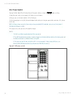
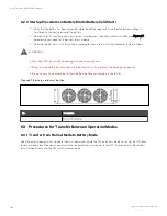
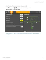
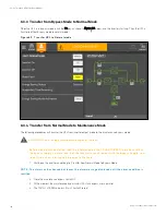
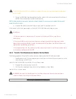
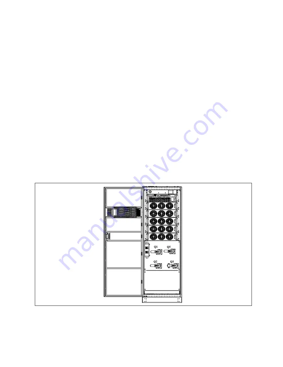
Opening the front door of the UPS cabinet reveals the power switches, as shown in Figure 6.1 below, including:
Q1: Rectifier input switch, which connects UPS to the main circuit power.
Q2: Bypass input switch, which connects UPS to the bypass.
Q3: Maintenance bypass switch (With error-proof operation buckle), which supplies power to the load when UPS is being
maintained.
N O T E: If th e system co n sists o f m o re th an two paralleled UP S m o du les, do n o t u se th e in tern al
m ain ten an ce bypass switch .
Q5: Output switch, which connects UPS output to the load.
N O T E:
1. Q 1, Q 2, an d Q 5 are o ptio n al wh ile Q 3 is stan dard.
2. F o r UP S m ain ten an ce an d du st rem o val, please in stall an d o th er switch es (in clu din g extern al
m ain ten an ce bypass switch es) wh en u sin g Q 3.
3. T h e in pu t-o u tpu t N lin e in side th e UP S is in ter-o perable. If th e extern al N lin e is n o t
disco n n ected du rin g m ain ten an ce, please pay atten tio n to safety.
F igu re 6.1 UP S po wer switch
6 Single UPS Operation Introduction
102
Vertiv™ Liebert® APM Plus User Manual
Summary of Contents for APM 0250kMK16FN02000
Page 1: ...Vertiv Liebert APM Plus User Manual 50 250 kVA UPS...
Page 8: ...vi This page intentionally left blank Vertiv Liebert APM Plus User Manual...
Page 30: ...2 Overview 22 This page intentionally left blank Vertiv Liebert APM Plus User Manual...
Page 97: ...5 Operator Control and Display Panel 89 Vertiv Liebert APM Plus User Manual...
Page 188: ...12 Specifications 180 This page intentionally left blank Vertiv Liebert APM Plus User Manual...

