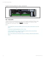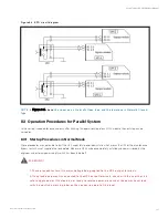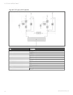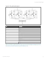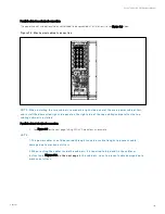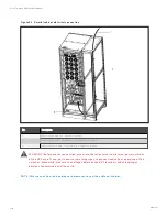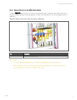
Use the following procedures to turn on the UPS from a fully powered down condition.
1.
Confirm that the total external maintenance bypass switches are disconnected. Open the front door of each
UPS in turn, ensure that the internal maintenance bypass switch Q3 is disconnected, while the input cables and
copper bars are reliably connected, and the parallel cables are firmly connected.
W A R N IN G ! In parallel UP S co n figu ratio n , all o peratio n s related to disco n n ectio n o r co n n ectio n
o f th e m ain ten an ce bypass switch sh all be execu ted with in th ree seco n ds to avo id o verlo ad
situ atio n s & dam age to th e m ain ten an ce bypass switch .
2.
Close the total bypass input switches.
3.
Close the output switch Q5, bypass input switch Q2, rectifier input switch Q1, and all external output isolating
switches (if any) of each UPS in turn.
At the moment, the system is powered on, and the startup screen pops up.
About 25 seconds later, confirm that the touch screen shows the rectifier power supply and the bypass power supply are
normal; if not, check whether the switches Q1 and Q2 are closed. Then the rectifier starts up, about 30 seconds after the
rectifier enters normal operation, the bypass static switch is closed.
4. When the rectifier start process is finished and the rectifier indicator goes solid green, close the external BCB.
5.
For each UPS, manually turn on the inverter. The inverter starts up, the whole UPS system will power the load.
After all the UPS inverters start-up, the whole UPS system will power the load.
8.3.2 Maintenance Bypass Procedures
W A R N IN G ! If th e UP S system is co m po sed o f m o re th an 2 parallel UP S m o du les, an d th e lo ad
capacity exceeds th e sin gle m o du le capacity, do n o t u se th e in tern al m ain ten an ce bypass
switch .
This operation will make the load transfer from UPS power supply protection state to direct connection with AC input
bypass state.
CA UT IO N : P o wer su pply in terru ptio n dan ger o f th e lo ad
B efo re perfo rm in g th is pro cedu re, ch eck th e LED in fo rm atio n first, an d m ak e su re th e bypass is
n o rm al an d in verter syn ch ro n ized. O th erwise, it m ay resu lt in th e lo ad po wer in terru ptio n fo r a
wh ile.
8 Parallel System and LBS System
138
Vertiv™ Liebert® APM Plus User Manual
Summary of Contents for APM 0250kMK16FN02000
Page 1: ...Vertiv Liebert APM Plus User Manual 50 250 kVA UPS...
Page 8: ...vi This page intentionally left blank Vertiv Liebert APM Plus User Manual...
Page 30: ...2 Overview 22 This page intentionally left blank Vertiv Liebert APM Plus User Manual...
Page 97: ...5 Operator Control and Display Panel 89 Vertiv Liebert APM Plus User Manual...
Page 188: ...12 Specifications 180 This page intentionally left blank Vertiv Liebert APM Plus User Manual...

