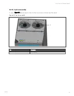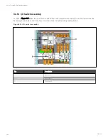
Parallel cabinet mechanical connection
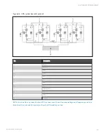
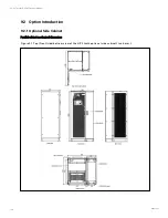
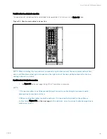
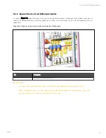
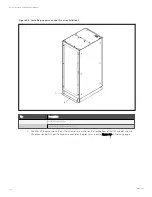
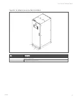
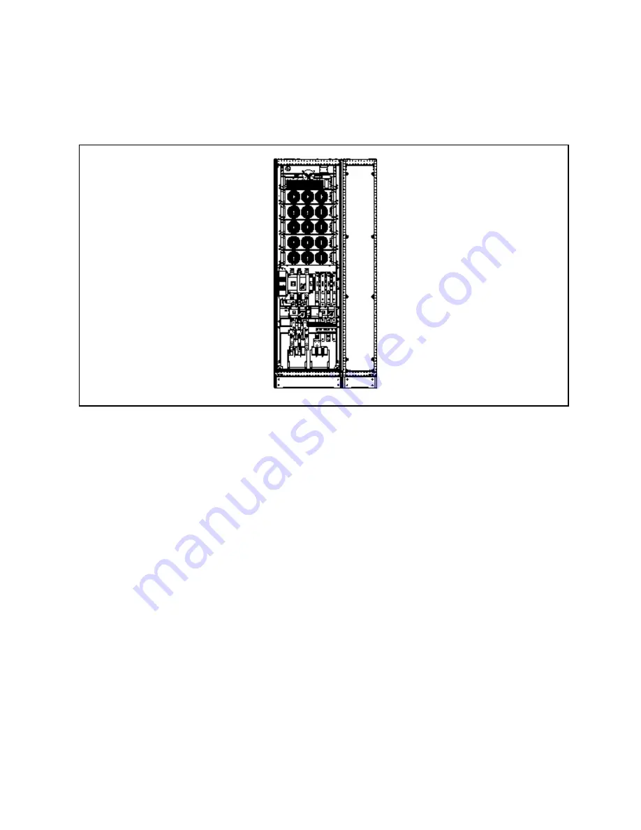
The power cabinet and optional side cabinet need to be connected at installation site, see Figure 9.2 below
F igu re 9.2 M ech an ical cabin et co n n ectio n
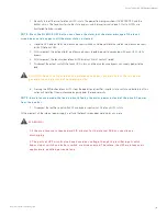
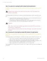
N O T E: W h en in stallin g th e two cabin ets, rem o ve th e righ t-side pan el o f th e m ain po wer cabin et first,
an d in stall th e dism an tled righ t-side pan el o n th e righ t-side o f th e to p cablin g cabin et after th e to p
cablin g cabin et is in stalled.
Parallel cabinet electrical connection
1.
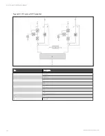
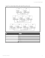
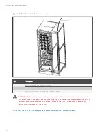
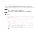
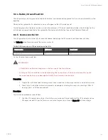
See Figure 9.3 on the next page, taking 250 kVA module as an example.
N O T E:
1. T h e po wer cables sh o u ld be ro u ted th ro u gh tu n n els o r cable tro u gh s to preven t cable
dam age du e to m ech an ical stress.
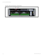
2. W h en ro u tin g th e cables in side th e cabin ets, it is requ ired to bin d an d fix th e cables as
in stru cted in
F igu re 9.3 o n th e n ext page
in th e cabin ets, so as to preven t cable dam age du e to
m ech an ical stress.
9 Options
149
Vertiv™ Liebert® APM Plus User Manual
Summary of Contents for APM 0250kMK16FN02000
Page 1: ...Vertiv Liebert APM Plus User Manual 50 250 kVA UPS...
Page 8: ...vi This page intentionally left blank Vertiv Liebert APM Plus User Manual...
Page 30: ...2 Overview 22 This page intentionally left blank Vertiv Liebert APM Plus User Manual...
Page 97: ...5 Operator Control and Display Panel 89 Vertiv Liebert APM Plus User Manual...
Page 188: ...12 Specifications 180 This page intentionally left blank Vertiv Liebert APM Plus User Manual...

