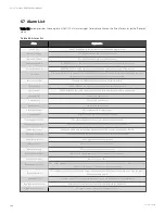
A larm
E xp lanation
Maint. Switch Closed
Maintenance bypass switch is closed
Bypass Switch Open
Bypass switch is open
Output Switch Open
Output switch is open
Charger Fault
Battery charger has failure
Discharger Curr. Limit
Discharge current is over limit, close the discharger
Autostart
After UPS shutdown at EOD, the inverter automatically starts upon mains restoration
Batt. Equalize Charge
The battery is forced to be in boost charge state
Rectifier DSP Update
Rectifier DSP software being updated
Rectifier FPGA Update
Rectifier FPGA software being updated
Inverter DSP Update
Inverter DSP software being updated
Inverter FPGA Update
Inverter FPGA software being updated
Bypass DSP Update
Bypass DSP software being updated
Bypass FPGA Update
Bypass FPGA software being updated
Monitor Update
Monitoring software being updated
Flash Operate Fail
Historical record not saved
Remote Turn On
Turn on the inverter through the service command
Remote Turn On Fail
Caused by invalid operation (maintenance bypass switch closed), DC bus or rectifier not ready
Remote Turn Off
Turn off the inverter through the service command
No Battery
Check the battery and battery connection
Discharger Fault
Bus voltage abnormal
Battery Reversed
Reconnect battery and check battery wiring
Battery Period Testing
The battery is under automatic periodic battery maintenance test (20% capacity discharge)
Batt. Capacity Testing
The user initiated a battery capacity test (100% capacity discharge)
Batt. Maint. Testing
The user initiated a maintenance test (20% capacity discharge)
Batt. End of Discharge
Inverter turned off due to battery EOD
Battery Overtemp.
The battery temperature is over limit
Low Battery Warning
Before the EOD, battery low pre-warning will occur. After this pre-warning, the battery will have the capacity for 3min
discharging with full load. The time is user-settable from 3min to 6min
On Generator
Dry contact signal, indicating generator connected
Battery Maintain
Capacity of the battery
Battery Ground Fault
Battery has ground fault
Batt. Room Temp. Abn.
Battery room has overtemperature (option included)
BCB1 Status Abnormal
Logic conflict between BCB1 drive signal and backfeed signal
BCB1 Closed
BCB1 state (closed)
T able 5.4 A larm list (co n tin u ed)
5 Touch Screen
102
Vertiv™ Liebert® APM Plus User Manual
Summary of Contents for APM Plus 0500kMK16FN02000
Page 1: ...Vertiv Liebert APM Plus User Manual 50 500 kVA UPS...
Page 8: ...vi This page intentionally left blank Vertiv Liebert APM Plus User Manual...
Page 34: ...2 Overview 26 This page intentionally left blank Vertiv Liebert APM Plus User Manual...
Page 45: ...Four switches 500 kVA 3 Mechanical Installation 37 Vertiv Liebert APM Plus User Manual...
Page 76: ...Figure 5 11 Customize the display 5 Touch Screen 68 Vertiv Liebert APM Plus User Manual...
Page 86: ...Figure 5 20 Enable module redundancy 5 Touch Screen 78 Vertiv Liebert APM Plus User Manual...
Page 91: ...Figure 5 24 Status Gauge setting options 5 Touch Screen 83 Vertiv Liebert APM Plus User Manual...
Page 92: ...5 Touch Screen 84 Vertiv Liebert APM Plus User Manual...
Page 94: ...5 Touch Screen 86 Vertiv Liebert APM Plus User Manual...
Page 95: ...Figure 5 26 Unit status Bypass details 5 Touch Screen 87 Vertiv Liebert APM Plus User Manual...
Page 96: ...Figure 5 27 Unit status Battery details 5 Touch Screen 88 Vertiv Liebert APM Plus User Manual...
Page 97: ...Figure 5 28 Unit status Load details 5 Touch Screen 89 Vertiv Liebert APM Plus User Manual...
Page 100: ...5 Touch Screen 92 Vertiv Liebert APM Plus User Manual...
Page 112: ...5 Touch Screen 104 This page intentionally left blank Vertiv Liebert APM Plus User Manual...
Page 184: ...12 Specifications 176 This page intentionally left blank Vertiv Liebert APM Plus User Manual...


