7.7.1 Battery Installation
1.
Before installation, check the battery appearance to ensure that there is no damage, inspect and count the
accessories, and carefully read this manual and the user manual or installation instruction provided by the
battery manufacturer.
2.
There shall be at least 10 mm gap between the batteries in vertical direction, to ensure the free circulation of
the ambient air of the batteries.
3.
Certain clearance shall be maintained between the battery top and the upper layer to facilitate the monitoring
and maintenance of the battery.
4. The batteries shall be installed from the bottom layer to top layer, so as to avoid a high gravity center. The
battery shall be properly installed and protected from vibration or shock.
7.8 Design of Battery Room
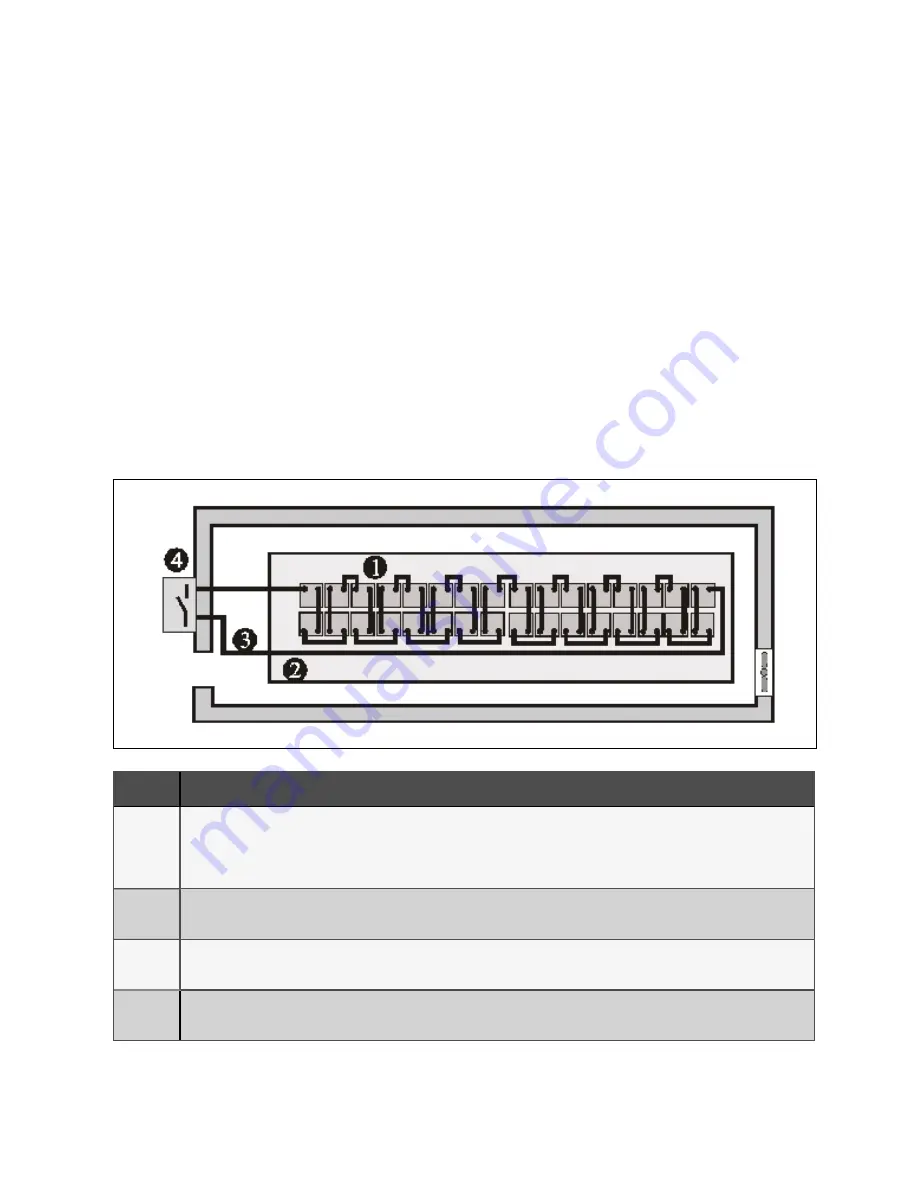
No matter which type of installation system is adopted, the following items shall be paid special attention to (refer to Figure
7.2 on the next page):
F igu re 7.1 Design o f battery ro o m
N o.
D es crip tion
1
Layout of cells
No matter which battery installation system is used, the battery shall be located in a matter that it will not contact two naked live parts with
the potential difference over 150 V at the same time. If it is unavoidable, insulated terminal shield and insulated cable shall be used for the
connection.
2
Workbench
The workbench (or pedal) must be skid-proof and insulated, and at least 1 m wide.
3
Wiring
All the wiring distances shall be minimized.
4
BCB
The BCB is installed in the wall-mounted box near the battery.
7 Battery
131
Vertiv™ Liebert® APM Plus User Manual
Summary of Contents for APM Plus 0500kMK16FN02000
Page 1: ...Vertiv Liebert APM Plus User Manual 50 500 kVA UPS...
Page 8: ...vi This page intentionally left blank Vertiv Liebert APM Plus User Manual...
Page 34: ...2 Overview 26 This page intentionally left blank Vertiv Liebert APM Plus User Manual...
Page 45: ...Four switches 500 kVA 3 Mechanical Installation 37 Vertiv Liebert APM Plus User Manual...
Page 76: ...Figure 5 11 Customize the display 5 Touch Screen 68 Vertiv Liebert APM Plus User Manual...
Page 86: ...Figure 5 20 Enable module redundancy 5 Touch Screen 78 Vertiv Liebert APM Plus User Manual...
Page 91: ...Figure 5 24 Status Gauge setting options 5 Touch Screen 83 Vertiv Liebert APM Plus User Manual...
Page 92: ...5 Touch Screen 84 Vertiv Liebert APM Plus User Manual...
Page 94: ...5 Touch Screen 86 Vertiv Liebert APM Plus User Manual...
Page 95: ...Figure 5 26 Unit status Bypass details 5 Touch Screen 87 Vertiv Liebert APM Plus User Manual...
Page 96: ...Figure 5 27 Unit status Battery details 5 Touch Screen 88 Vertiv Liebert APM Plus User Manual...
Page 97: ...Figure 5 28 Unit status Load details 5 Touch Screen 89 Vertiv Liebert APM Plus User Manual...
Page 100: ...5 Touch Screen 92 Vertiv Liebert APM Plus User Manual...
Page 112: ...5 Touch Screen 104 This page intentionally left blank Vertiv Liebert APM Plus User Manual...
Page 184: ...12 Specifications 176 This page intentionally left blank Vertiv Liebert APM Plus User Manual...


