7.10 BCB Cabinet (Optional)
The UPS has three kinds of BCB matching cabinets, and the user can choose the cabinet you need according to actual
requirement. The BCB cabinet can also electrically isolate the UPS from the battery to minimize the danger of the service
personnel at work.
The BCB provides the following functions:
•
Short circuit protection and EOD protection. The BCB opens automatically when the battery voltage drops to
the EOD voltage point.
•
Support the UPS EPO function. The BCB opens automatically when the EPO switch on the touchscreen of the
UPS is pressed.
Three kinds of BCB cabinets:
Overall BCB cabinet
One 1600 A switch included for single battery string use or bus switch of several battery strings.
Divided BCB cabinet (three independent switches included)
Three 800 A switches included for three groups of battery string use, and each switch can independently control the
connection of each battery string.
Divided BCB cabinet (four independent switches included)
Four 630 A switches included for the four groups of battery string use, and each switch can independently control the
connection of each battery string.
Mechanical specifications of the BCB cabinet is provided in Table 7.3 below.
D im ens ions (H × W × D ) (m m )
Weig ht (kg )
Recom m end ed s crew
2000 × 600 × 987
250
M16
T able 7.3 P aram eters o f B CB cabin et
The BCB cabinet should be installed as close as possible to the battery. It can be installed on a horizontal surface.
Besides the local regulations, to enable routine operation of switches in the BCB cabinet within the BCB cabinet, it is
recommended that clearance around the front of the UPS should be larger than 1200 mm and enough to enable free
passage of personnel with the door fully open. Meanwhile, maintain a clearance of at least 500 mm at the back of the
cabinet to permit adequate circulation of air coming out of the UPS.
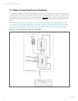
To install and connect the BCB cabinet refer to Figure 7.3 on the next page to Figure 7.7 on page 137. There are connection
terminals in the BCB cabinet for connecting the power cables from the UPS and battery. Before powering on the UPS, lead
out the internal signal cables from the BCB cabinet to connect the left port of J22 on the bypass control module.
N O T E: T h e B CB cabin et can u se to p an d bo tto m cable en try. It pro vides two big an d o n e sm all cable
en try h o les o n bo th th e to p an d bo tto m plate. T h e big o n es are fo r po wer cable en try, an d th e sm all o n e
is fo r sign al cable en try. A fter co n n ectio n , tak e appro priate m easu res to seal th e cable en try h o les.
N O T E: T h e sign al cable W 8 12 m u st ru n separate fro m th e battery po wer cables. W 8 12 is a sh ield cable,
bo th en ds o f its sh ield layer m u st be co n n ected to th e en clo su re. T h e UP S an d B CB cabin et m u st be
earth ed separately.
N O T E: M ak e su re th at th e UP S rectifier h as started befo re clo sin g th e B CB .
7 Battery
133
Vertiv™ Liebert® APM Plus User Manual
Summary of Contents for APM Plus 0500kMK16FN02000
Page 1: ...Vertiv Liebert APM Plus User Manual 50 500 kVA UPS...
Page 8: ...vi This page intentionally left blank Vertiv Liebert APM Plus User Manual...
Page 34: ...2 Overview 26 This page intentionally left blank Vertiv Liebert APM Plus User Manual...
Page 45: ...Four switches 500 kVA 3 Mechanical Installation 37 Vertiv Liebert APM Plus User Manual...
Page 76: ...Figure 5 11 Customize the display 5 Touch Screen 68 Vertiv Liebert APM Plus User Manual...
Page 86: ...Figure 5 20 Enable module redundancy 5 Touch Screen 78 Vertiv Liebert APM Plus User Manual...
Page 91: ...Figure 5 24 Status Gauge setting options 5 Touch Screen 83 Vertiv Liebert APM Plus User Manual...
Page 92: ...5 Touch Screen 84 Vertiv Liebert APM Plus User Manual...
Page 94: ...5 Touch Screen 86 Vertiv Liebert APM Plus User Manual...
Page 95: ...Figure 5 26 Unit status Bypass details 5 Touch Screen 87 Vertiv Liebert APM Plus User Manual...
Page 96: ...Figure 5 27 Unit status Battery details 5 Touch Screen 88 Vertiv Liebert APM Plus User Manual...
Page 97: ...Figure 5 28 Unit status Load details 5 Touch Screen 89 Vertiv Liebert APM Plus User Manual...
Page 100: ...5 Touch Screen 92 Vertiv Liebert APM Plus User Manual...
Page 112: ...5 Touch Screen 104 This page intentionally left blank Vertiv Liebert APM Plus User Manual...
Page 184: ...12 Specifications 176 This page intentionally left blank Vertiv Liebert APM Plus User Manual...


