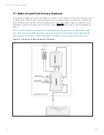
N O T E: Q 1, Q 2, an d Q 5 are o ptio n al wh ile Q 3 is stan dard.
8.2.3 External Protective Device
W A R N IN G !
1. High earth leak age cu rren t: Earth co n n ectio n is critical befo re co n n ectin g th e in pu t su pply
(in clu din g bo th m ain s su pply an d battery).
2. T h e equ ipm en t m u st be earth ed in acco rdan ce with th e lo cal electrical co de o f practice.
Refer to External Protective Device.
8.2.4 Power Cable
The power cable wiring is similar to that of the UPS module. Refer to Wiring of Power Cable.
The bypass and rectifier input supplies must use the same neutral line input terminal. If the input has a current leakage
protective device, the current leakage protective device must be fitted upstream of the neutral line input terminal.
N O T E: T h e po wer cables (in clu din g th e bypass in pu t cables an d UP S o u tpu t cables) o f each UP S
m o du le sh o u ld be o f th e sam e len gth an d specificatio n s to facilitate lo ad sh arin g.
8.2.5 Parallel Cable
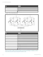
Shielded and double-insulated parallel cables available in lengths 5 m, 10 m and 15 m must be interconnected in a ring
configuration between the UPS modules, as shown in Figure 8.2 below. Method: Connect a module parallel cable from its
PARA1 port to the PARA2 port of another module. Follow this method to connect other parallel cables.
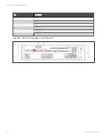
The parallel port J3 is provided on the front panel of the bypass control module, as shown in Figure 8.3 on the next page.
The ring connection ensures the reliability of the control of the parallel system. Be sure to verify the reliable cable
connection before starting up the system!
F igu re 8 .2 P arallel sign al cables co n n ectio n (P arallel system )
N o.
D es crip tion
1
PARA1
2
PARA2
3
LBS
8 Parallel System and LBS System
143
Vertiv™ Liebert® APM Plus User Manual
Summary of Contents for APM Plus 0500kMK16FN02000
Page 1: ...Vertiv Liebert APM Plus User Manual 50 500 kVA UPS...
Page 8: ...vi This page intentionally left blank Vertiv Liebert APM Plus User Manual...
Page 34: ...2 Overview 26 This page intentionally left blank Vertiv Liebert APM Plus User Manual...
Page 45: ...Four switches 500 kVA 3 Mechanical Installation 37 Vertiv Liebert APM Plus User Manual...
Page 76: ...Figure 5 11 Customize the display 5 Touch Screen 68 Vertiv Liebert APM Plus User Manual...
Page 86: ...Figure 5 20 Enable module redundancy 5 Touch Screen 78 Vertiv Liebert APM Plus User Manual...
Page 91: ...Figure 5 24 Status Gauge setting options 5 Touch Screen 83 Vertiv Liebert APM Plus User Manual...
Page 92: ...5 Touch Screen 84 Vertiv Liebert APM Plus User Manual...
Page 94: ...5 Touch Screen 86 Vertiv Liebert APM Plus User Manual...
Page 95: ...Figure 5 26 Unit status Bypass details 5 Touch Screen 87 Vertiv Liebert APM Plus User Manual...
Page 96: ...Figure 5 27 Unit status Battery details 5 Touch Screen 88 Vertiv Liebert APM Plus User Manual...
Page 97: ...Figure 5 28 Unit status Load details 5 Touch Screen 89 Vertiv Liebert APM Plus User Manual...
Page 100: ...5 Touch Screen 92 Vertiv Liebert APM Plus User Manual...
Page 112: ...5 Touch Screen 104 This page intentionally left blank Vertiv Liebert APM Plus User Manual...
Page 184: ...12 Specifications 176 This page intentionally left blank Vertiv Liebert APM Plus User Manual...


