1.
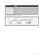
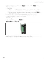
Insert the UF-RS485 card into the UPS.
a. Remove the Intellislot port cover on the front panel of the bypass module. Save the screws.
b. Align the UF-RS485 card with the Intellislot port, insert the card into the port along the grooves on both
sides of the port.
c. Fix the UF-RS485 card through the fixing holes on the UF-RS485 card panel with the screws obtained
when removing the Intellislot port cover previously.
2.
Connect the cable. Users can select a standard network cable in proper length as the connecting cable
according to needs.
a. Insert one end of the standard network cable into the RJ45 port 1 or RJ45 port 2 of the UF-RS485 card.
b. Insert the other end of the standard network cable to the corresponding port of the user equipment.
W A R N IN G !
1. T h e R J 45 po rts o f th e UF -R S48 5 card m u st co n n ect to SELV circu it. F ailu re to o bserve th is
co u ld cau se dam age to th e card an d even resu lt in safety acciden ts.
2. T h e co n n ectin g cable o f th e UF -R S48 5 card an d th e extern al equ ipm en t m u st be a do u ble-
en d sh ielded cable.
Troubleshooting
Fault: The UF-RS485 output signal does not change with the UPS status.
Action to take: Ensure that the UF-RS485 card is properly inserted into the Intellislot port and the cable is properly
connected.
9.2.7 BCB Cabinet
Refer to BCB Cabinet (Optional) for details.
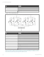
9.2.8 Parallel Cable
Shielded and double-insulated parallel cables available in lengths of 5 m, 10 m and 15 m must be interconnected in a ring
configuration between the UPS modules, as shown in Figure 8.2 on page 143. Method: Connect a module parallel cable from
its PARA1 port to the PARA2 port of another module. Follow this method to connect other parallel cables.
The ring connection ensures the reliability of the control of the parallel system. Be sure to verify the reliable cable
connection before starting up the system!
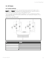
9.2.9 LBS Cable
Shielded and double-insulated parallel control cables (LBS1 and LBS2) available in lengths of 10m, 15m and 20m. The LBS
cable must be interconnected in a branch configuration between LBS1 and LBS2 of any UPS modules, as shown in, as shown
in Figure 8.7 on page 151.
9.2.10 Shorting Copper Bar Kit
For the UPS with shorting copper bar of common input configuration, the user should select the shorting copper bar kit to
short the mains input and bypass input.
9 Options
162
Vertiv™ Liebert® APM Plus User Manual
Summary of Contents for APM Plus 0500kMK16FN02000
Page 1: ...Vertiv Liebert APM Plus User Manual 50 500 kVA UPS...
Page 8: ...vi This page intentionally left blank Vertiv Liebert APM Plus User Manual...
Page 34: ...2 Overview 26 This page intentionally left blank Vertiv Liebert APM Plus User Manual...
Page 45: ...Four switches 500 kVA 3 Mechanical Installation 37 Vertiv Liebert APM Plus User Manual...
Page 76: ...Figure 5 11 Customize the display 5 Touch Screen 68 Vertiv Liebert APM Plus User Manual...
Page 86: ...Figure 5 20 Enable module redundancy 5 Touch Screen 78 Vertiv Liebert APM Plus User Manual...
Page 91: ...Figure 5 24 Status Gauge setting options 5 Touch Screen 83 Vertiv Liebert APM Plus User Manual...
Page 92: ...5 Touch Screen 84 Vertiv Liebert APM Plus User Manual...
Page 94: ...5 Touch Screen 86 Vertiv Liebert APM Plus User Manual...
Page 95: ...Figure 5 26 Unit status Bypass details 5 Touch Screen 87 Vertiv Liebert APM Plus User Manual...
Page 96: ...Figure 5 27 Unit status Battery details 5 Touch Screen 88 Vertiv Liebert APM Plus User Manual...
Page 97: ...Figure 5 28 Unit status Load details 5 Touch Screen 89 Vertiv Liebert APM Plus User Manual...
Page 100: ...5 Touch Screen 92 Vertiv Liebert APM Plus User Manual...
Page 112: ...5 Touch Screen 104 This page intentionally left blank Vertiv Liebert APM Plus User Manual...
Page 184: ...12 Specifications 176 This page intentionally left blank Vertiv Liebert APM Plus User Manual...


