2.2.4 UPS Power Supply Switch Configuration
The UPS equipped with single switch: maintenance bypass switch Q3.
The UPS equipped with four switches: rectifier input switch Q1, bypass input switch Q2, maintenance bypass switch Q3, and
output switch Q5.
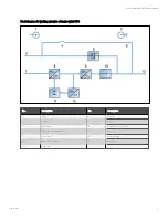
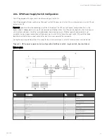
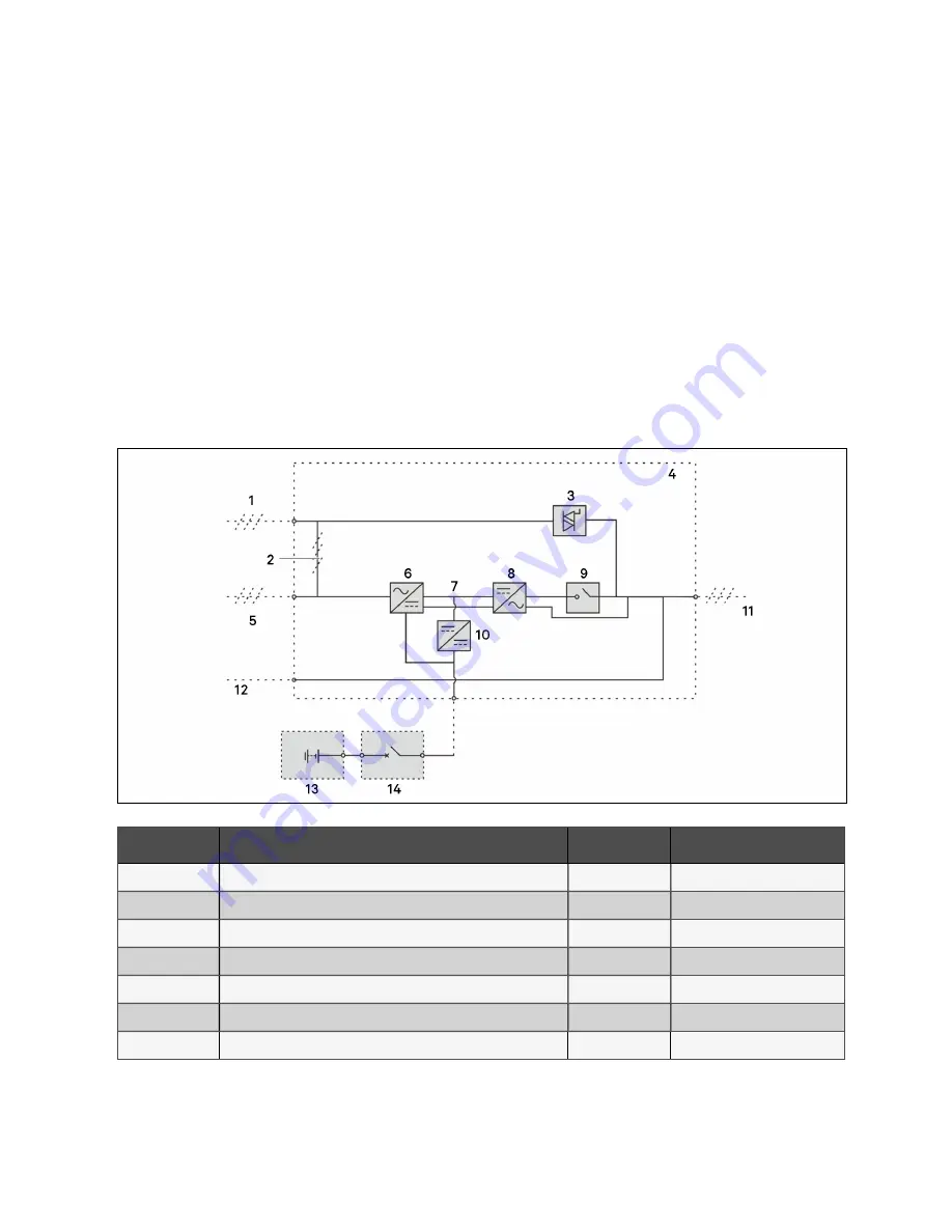
Figure 2.2 below describes the block diagram of the UPS module. The UPS has split bypass configuration (that is, the
bypass adopts independent mains input) and common input configuration. In split bypass configuration, the static bypass
and maintenance bypass share the same independent bypass power supply. Where a separate power source is not
available, the input supply connections of the bypass input switch (Q2) and rectifier input switch (Q1) would be linked
together to make the bypass input and rectifier input use mains power of the same route.
During the normal operation of the UPS, except for the maintenance bypass switch Q3, other switches shall be closed.
F igu re 2.2 UP S po wer su pply switch co n figu ratio n (with o u t switch , sin gle switch , fo u r switch es)
Without switch
N o.
D es crip tion
N o.
D es crip tion
1
Bypass input
8
Inverter
2
Shorting copper bar of input configuation
9
Inverter switch
3
Static switch
10
Charger
4
UPS
11
UPS output
5
Mains input
12
Neutral line input
6
Rectifier
13
Battery
7
DC bus
14
BCB
2 Overview
15
Vertiv™ Liebert® APM Plus User Manual
Summary of Contents for APM Plus 0500kMK16FN02000
Page 1: ...Vertiv Liebert APM Plus User Manual 50 500 kVA UPS...
Page 8: ...vi This page intentionally left blank Vertiv Liebert APM Plus User Manual...
Page 34: ...2 Overview 26 This page intentionally left blank Vertiv Liebert APM Plus User Manual...
Page 45: ...Four switches 500 kVA 3 Mechanical Installation 37 Vertiv Liebert APM Plus User Manual...
Page 76: ...Figure 5 11 Customize the display 5 Touch Screen 68 Vertiv Liebert APM Plus User Manual...
Page 86: ...Figure 5 20 Enable module redundancy 5 Touch Screen 78 Vertiv Liebert APM Plus User Manual...
Page 91: ...Figure 5 24 Status Gauge setting options 5 Touch Screen 83 Vertiv Liebert APM Plus User Manual...
Page 92: ...5 Touch Screen 84 Vertiv Liebert APM Plus User Manual...
Page 94: ...5 Touch Screen 86 Vertiv Liebert APM Plus User Manual...
Page 95: ...Figure 5 26 Unit status Bypass details 5 Touch Screen 87 Vertiv Liebert APM Plus User Manual...
Page 96: ...Figure 5 27 Unit status Battery details 5 Touch Screen 88 Vertiv Liebert APM Plus User Manual...
Page 97: ...Figure 5 28 Unit status Load details 5 Touch Screen 89 Vertiv Liebert APM Plus User Manual...
Page 100: ...5 Touch Screen 92 Vertiv Liebert APM Plus User Manual...
Page 112: ...5 Touch Screen 104 This page intentionally left blank Vertiv Liebert APM Plus User Manual...
Page 184: ...12 Specifications 176 This page intentionally left blank Vertiv Liebert APM Plus User Manual...


