U PS
p ower
(kV A )
Rated current (A )
Bus s tud b olt/nut s p ecification
M ax. inp ut
current
1,2
O utp ut/b yp as s current
2
at full
load
Battery
d is charg e
3&4
current (+, - , N ) at
rated b attery
voltag e
Inp ut, b attery,
outp ut,
b yp as s /PE
cab le
Recom m end ed
torq ue (N m )
380 V
4 0 0 V
4 15 V
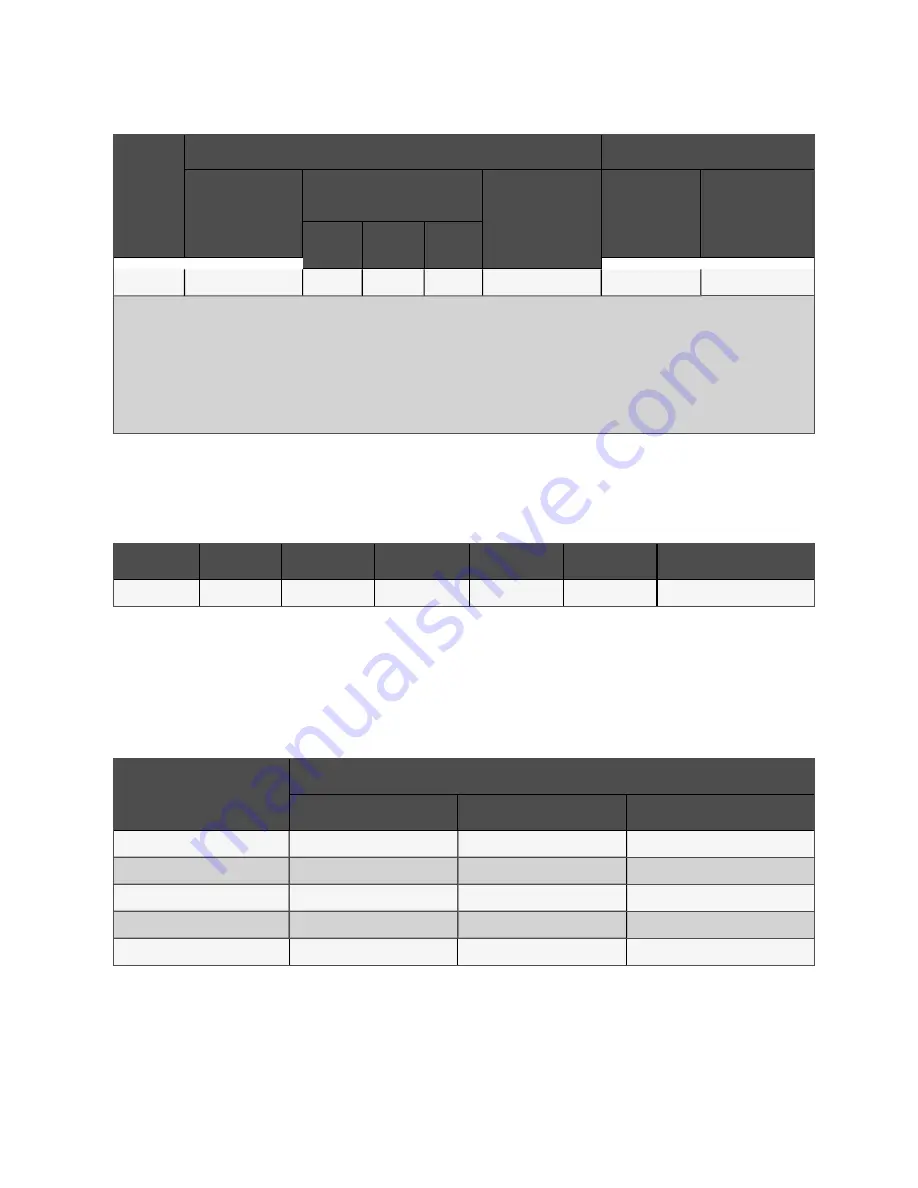
500 kVA
995
760
726
696
1371
M12
39±10%
Note:
1. Max. input current is calculated according to the low voltage input of 176 V and 100% load percentage.
2. Max. output/bypass current is calculated according to the rated voltage and 100% load percentage.
3. The battery discharge current is calculated according to battery cell number of 40, EOD voltage of 1.6 V and 100% load percentage.
4. .For 500 kVA, load deration is applicable when 28 - 38 no of batteries are configured such as @ 28 nos - 70% capacity, @ 30 nos-75%capacity, @ 32 nos-
80% capacity, @ 34 nos- 85% capacity, @ 36 nos- 90% capacity, @ 38 nos- 95% capacity.
T able 4.1 M ax. steady state A C an d DC cu rren ts
4.1.3 Recommended CSA of UPS Cable
The recommended CSA of the UPS cable is listed in Table 4.2 below.
M od el
Inp ut
O utp ut
Byp as s
N eutral line
E arth cab le
Battery
500 kVA
3 x 150
3 x 150
3 x 150
3 x 150
2 x 150
See
T able 4.2 R eco m m en ded CSA o f th e UP S sin gle m o du le cable (u n it: m m
2
, am bien t tem peratu re: 25 °C)
4.1.4 Selection of UPS I/O Switch and Battery Switch
The user can select the switch according to actual needs. Refer to Table 4.1 above for I/O current and battery current value.
4.1.5 Distance between the UPS Connection Point and Floor
U PS connection p oint
M in. d is tance (m m )
Without s witch
S ing le s witch
Four s witches
Rectifier input
1743
1743
648
Bypass input
1743
1743
1225
AC Output
1743
1743
1495/1559
Battery supply
1743
1743
848/792
PE terminal
1835
1835
1348
T able 4.3 M in . distan ce between UP S co n n ectio n po in t an d flo o r
4 Electrical Installation
40
Vertiv™ Liebert® APM Plus User Manual
Summary of Contents for APM Plus 0500kMK16FN02000
Page 1: ...Vertiv Liebert APM Plus User Manual 50 500 kVA UPS...
Page 8: ...vi This page intentionally left blank Vertiv Liebert APM Plus User Manual...
Page 34: ...2 Overview 26 This page intentionally left blank Vertiv Liebert APM Plus User Manual...
Page 45: ...Four switches 500 kVA 3 Mechanical Installation 37 Vertiv Liebert APM Plus User Manual...
Page 76: ...Figure 5 11 Customize the display 5 Touch Screen 68 Vertiv Liebert APM Plus User Manual...
Page 86: ...Figure 5 20 Enable module redundancy 5 Touch Screen 78 Vertiv Liebert APM Plus User Manual...
Page 91: ...Figure 5 24 Status Gauge setting options 5 Touch Screen 83 Vertiv Liebert APM Plus User Manual...
Page 92: ...5 Touch Screen 84 Vertiv Liebert APM Plus User Manual...
Page 94: ...5 Touch Screen 86 Vertiv Liebert APM Plus User Manual...
Page 95: ...Figure 5 26 Unit status Bypass details 5 Touch Screen 87 Vertiv Liebert APM Plus User Manual...
Page 96: ...Figure 5 27 Unit status Battery details 5 Touch Screen 88 Vertiv Liebert APM Plus User Manual...
Page 97: ...Figure 5 28 Unit status Load details 5 Touch Screen 89 Vertiv Liebert APM Plus User Manual...
Page 100: ...5 Touch Screen 92 Vertiv Liebert APM Plus User Manual...
Page 112: ...5 Touch Screen 104 This page intentionally left blank Vertiv Liebert APM Plus User Manual...
Page 184: ...12 Specifications 176 This page intentionally left blank Vertiv Liebert APM Plus User Manual...


