Challenger 3000 w/ iCOM
- ii -
September 2011
10.
Humidifier Section .......................................................................... 43
10.1.
Drain Options .............................................................................. 43
10.2.
Infrared ...................................................................................... 44
10.2.1.
IR Assembly ............................................................................ 45
10.2.2.
009261 Socket Assembly ........................................................... 46
10.2.3.
035-0342 Hum Reset Safety ...................................................... 46
10.2.4.
Valve Solenoid Autoflush ........................................................... 46
10.2.5.
009-0262 Socket Assembly........................................................ 46
10.3.
Steam Generating ........................................................................ 47
10.3.1.
Humidifier Canister ................................................................... 48
11.
Piping Section................................................................................. 49
11.1.
Chilled Water .............................................................................. 49
11.1.1.
Upflow: Chilled Water ............................................................... 49
11.1.2.
Upflow: CW HP w/ HWRH .......................................................... 50
11.1.3.
Upflow: CW High Pressure ......................................................... 51
11.1.4.
Upflow: CW w/ HWRH ............................................................... 52
11.1.5.
Upflow: CW w/ FS .................................................................... 53
11.1.6.
Downflow: Chilled Water ........................................................... 55
11.1.7.
Downflow: CW High Pressure ..................................................... 56
11.1.8.
Downflow: CW w/ Hot Water Reheat ........................................... 57
11.1.9.
Downflow: CW HP w/ HWRH ...................................................... 58
11.1.1.
Downflow: CW w/ FS ................................................................ 59
11.2.
Air Cooled ................................................................................... 61
11.2.1.
Suction Line Assembly 3/5T ....................................................... 63
11.2.2.
Liquid Line Assembly 3T A D/U (14142G1) ................................... 63
11.2.3.
Discharge Line Assembly D/U ..................................................... 64
11.2.4.
Hot Gas ASM 3/5T (141141G1) .................................................. 64
11.2.5.
Discharge Line Assembly (179738G2) ......................................... 65
11.2.6.
Digital Solenoid Valve Assembly ................................................. 65
11.3.
Water/Glycol ............................................................................... 66
11.3.1.
Water/Glycol Cooled POE ........................................................... 66
11.3.2.
Liquid Line Assembly 3T D/U 3000 (141143G1) ............................ 67
11.3.3.
Liquid Line Assembly ½ (196665G1-G2) ...................................... 67
11.3.4.
Discharge Line Assembly 3T/5T C3000 ........................................ 68
11.3.5.
Water/Glycol Cooled R-407C ...................................................... 69
11.3.6.
Digital Solenoid Valve Assembly ................................................. 70
11.3.7.
Hot Gas Reheat ........................................................................ 71
11.3.8.
Suction Assembly (196088G1) ................................................... 72
11.4.
Glycool Cooled ............................................................................. 73
11.4.1.
Standard/High Pressure ............................................................ 73
11.4.2.
Suction Line Assembly (196693G1) ............................................ 74
11.4.3.
Digital ..................................................................................... 75
11.4.4.
Suction Line Assembly 5T Upflow (196693G1) .............................. 76
11.4.5.
Scroll ...................................................................................... 76
11.5.
Evaporator .................................................................................. 78
11.5.1.
Upflow .................................................................................... 78
11.5.2.
Downflow ................................................................................ 79
11.5.3.
Suction Line Assembly 3T/5T Evap Upflow (141144) ..................... 80
11.5.4.
Liquid Line Assembly 3T/5T Evap Upflow (141145) ....................... 81
11.5.5.
Suction Assembly (196835G1) ................................................... 82
11.5.6.
Liquid Assembly (196836G1) ..................................................... 83
12.
Reheat Section ............................................................................... 84
13.
Parts Gallery ................................................................................... 85
14.
Revision Page ................................................................................. 92
Summary of Contents for Challenger 3000
Page 5: ...Challenger 3000 w iCOM 2 September 2011 2 Model Number Definition...
Page 9: ...Challenger 3000 w iCOM 6 September 2011...
Page 16: ...September 2011 13...
Page 19: ...Challenger 3000 w iCOM 16 September 2011 7 3 EP Compressor...
Page 21: ...Challenger 3000 w iCOM 18 September 2011 7 4 EP Backpanel...
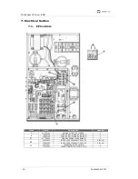
Page 24: ...Electrical Section September 2011 21 7 5 EP Humidifier...
Page 27: ...Challenger 3000 w iCOM 24 September 2011 7 7 EP Motor...
Page 29: ...Challenger 3000 w iCOM 26 September 2011 7 8 EP Reheat...


