Chapter 7 Parallel System And LBS System 101
Liebert EXM 80kVA ~ 200kVA UPS User Manual
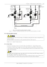
Input power
supply
Mains input
L1,L2,L3,N
BCB
Battery 1
Rectifier
Charger
Inverter
Static
switch
Q1
Q5
QE1
QOP
L1, L2,L3,N
Q3
Output distribution
Q2
External
bypass switch
Exte
rnal
maintenance
bypass
Mains input
L1,L2,L3,N
BCB
Battery 2
Rectifier
Charger
Inverter
Static
switch
Q1
Q5
QE2
QBP
L1, L2,L3,N
Q3
Q2
To load
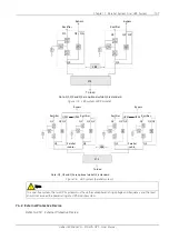
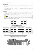
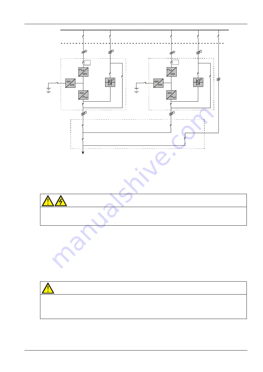
Note: Q1, Q2 and Q5 are optional while Q3 is standard
UPS 1
UPS 2
Figure 7-1 Schematic of typical parallel system (with common input, separate batteries and output)
7.2.3
External protective device
Warning
1. High earth leakage current: Earth connection is critical before connecting the input supply (including both mains
supply and battery).
2. The equipment must be earthed in accordance with the local electrical code of practice.
Refer to
3.1.9 External Protective Device
.
7.2.4
Power Cable
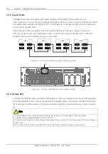
The power cable wiring is similar to that of the UPS module. Refer to
3.1 Wiring Of Power Cable
.
The bypass and rectifier input supplies must use the same neutral line input terminal. If the input has a
current leakage protective device, the current leakage protective device must be fitted upstream of the
neutral line input terminal
.
Note
1. The power cables (including the bypass input cables and UPS output cables) of each UPS module should be of
the same length and specifications to facilitate load sharing.
2. The UPS adopts common input configuration and split bypass configuration. If the mains input and bypass input
come from two different transformers, then these two transformers should share one grounding grid.
Summary of Contents for EXM 0080kTK16FN01000
Page 2: ......
Page 14: ......
Page 132: ...118 Chapter 8 Options Liebert EXM 80kVA 200kVA UPS User Manual...

