120 Chapter 8 Options
Liebert EXM 80kVA ~ 200kVA UPS User Manual
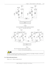
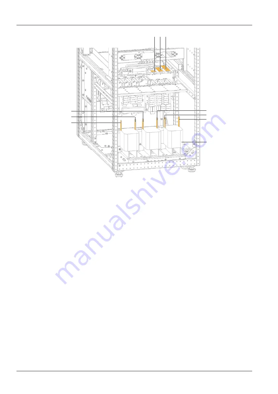
bA
bB
bC
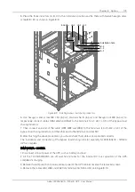
Inductor
LA-1
LB-1
LC-1
LB-2
LC-2
LA-2
A
B
C
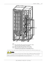
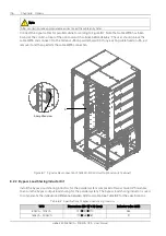
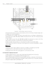
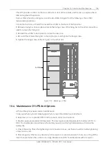
Figure 8-10 Position of bypass load sharing inductors
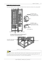
5. Place the three inductors (A, B, C) in the installation position and fix them with twelve hexagon sems
screw M8 × 20, as shown in Figure 8-10.
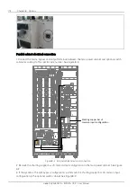
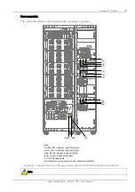
6. Use hexagon sems screw M8 × 20 (6 pcs), plain washer 8 (6 pcs) and hexagon nut M8 (6 pcs) to
respectively connect cables (W61, W62 and W63) to the terminals (LA-1, LB-1, LC-1) of the bypass load
sharing inductors.
7. Then connect one end of the cable (W81, W82 and W83) to the terminals (LA-2, LB-2, LC-2) of the
bypass load sharing inductors, and the other end to the terminals (bA, bB, bC).
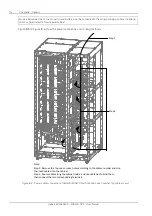
8. After finishing the above procedures, you should check that cables are connected correctly.
The installation and connection of the bypass load sharing inductor assembly for EXM 160kVA ~ 200kVA
UPS is complete.
Maintenance
1. Keep the connections tight. Tighten all connections in installation, and periodically check them.
2. Keep the inductors clean. Maintain the inductors free of dust and moisture.
3. Keep good records. Inform the service engineer for on-site maintenance in time.
8.2.3
Battery Temperature Sensor Kit
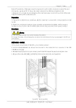
A battery temperature sensor is used to measure the battery temperature. At this moment, the
temperature sensor is connected with the UPS internal logic circuit.
With this feature fitted, the nominal float voltage supplied to the battery is adjusted so as to be inversely
proportional to the ambient temperature of the battery cabinet or battery room. This prevents the battery
being over charged at high ambient temperatures.
Summary of Contents for EXM 0080kTK16FN01000
Page 2: ......
Page 14: ......
Page 132: ...118 Chapter 8 Options Liebert EXM 80kVA 200kVA UPS User Manual...

