C h apter 1 O verview 7
L iebert E X S 30 kV A A n d 4 0 kV A U P S U ser M an ual
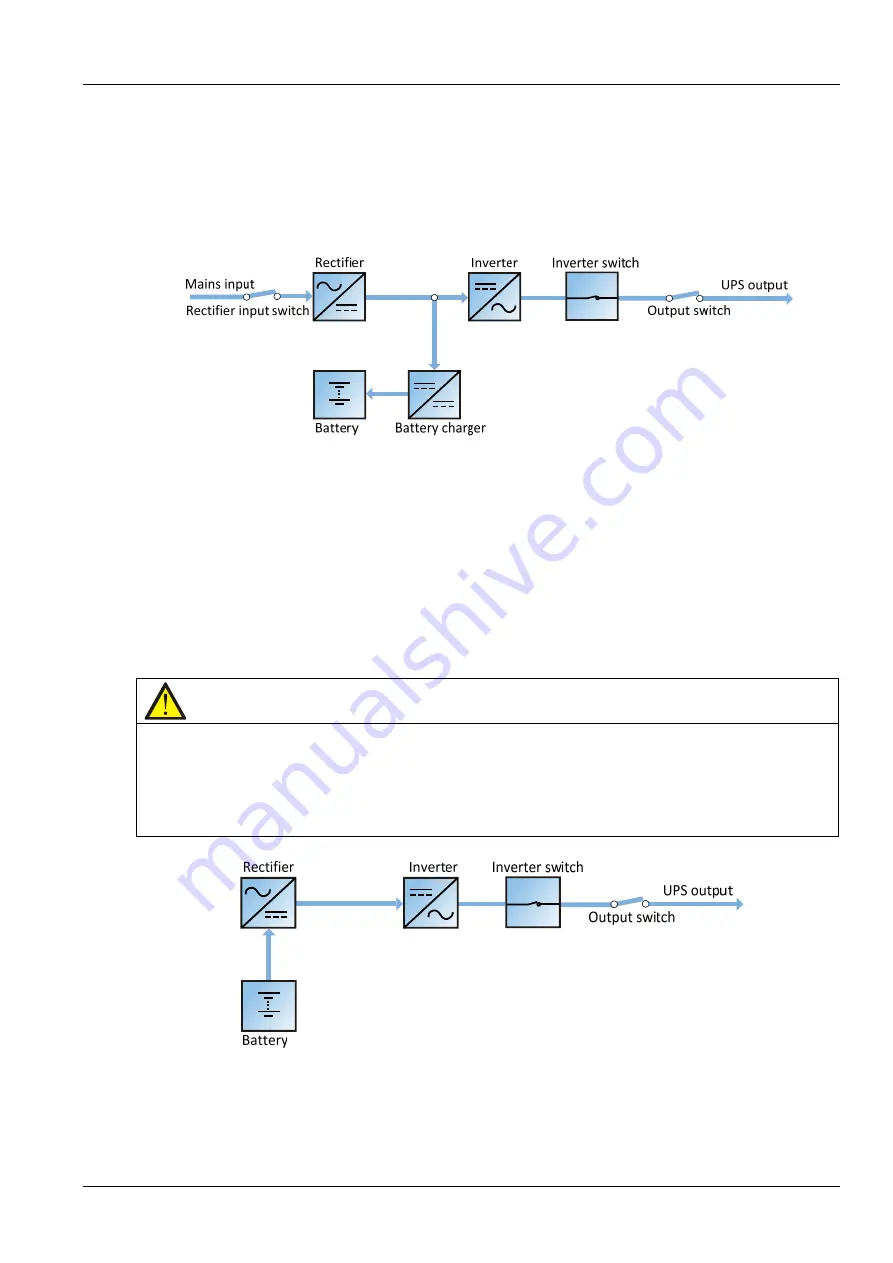
N o rm a l m o d e
W hen the m ains input is norm al, the load is supplied w ith voltage-stabilizing and frequency-stabilizing
pow er by the m ains after processing of the rectifier and the inverter, and m eanw hile, the charger is charging
the battery. T he operation m ode is N orm al m ode.
In N orm al m ode, the run indicator (g reen) is on, the alarm indicator is off, and the buzzer is silenced.
Figure 1-3 Sch em atic diagram of n orm al m ode
B a tte ry m o d e
U pon m ains failure or voltag e out of range, the rectifier and internal charger w ill stop running , and the
battery w ill supply pow er to the load throug h the inverter. W hen the m ains is recovered, the system w ill
autom atically transfer back to the norm al m ode w ithout any m anual intervention, and the pow er to the load
w ill not be interrupted.
In B attery m ode, the run indicator (g reen) is on, alarm indicator (yellow ) is on, and the buzzer beeps every
second. T he 'C urrent' page in LC D w ill display 'O n B attery'.
N o te
1. T h e battery h as been fully ch arg ed before d elivery. H ow ever, som e loss of capacity is in evitable durin g
tran sportation an d storag e. T herefore, it is im portan t to ch arg e th e battery for eig h t h ours before p uttin g th e U P S
in to operation for th e first tim e, to en sure it is c apable of providin g adequate backup tim e.
2. T h e battery cold start fun ction m ay also be used to start th e U P S from th e B attery (providin g it is fully ch arg ed)
m ode in th e even t of a m ain s failure. T h is m ean s th at th e battery pow er can be used in depen den tly to im prove th e
system availability, to a certain exten t.
Figure 1-4 Schem atic diagram of battery m ode


