C h apter 6 P arallel System A n d L B S System 6 5
L iebert E X S 30 kV A A n d 4 0 kV A U P S U ser M an ual
6 .3.1
P relim inary C heck s
M ake sure that correct parallel cable option has been selected, and that the m odule ratings, m odel, and
softw are and hardw are releases are consistent.
W a rn in g
T o achieve coordin ated operation of th e m odules in th e parallel system , it is required to con fig ure each m odule
separately usin g V ertiv settin g softw are. T h is m ust b e don e b y V ertiv service person n el.
6.3.2
C ab inet Installation
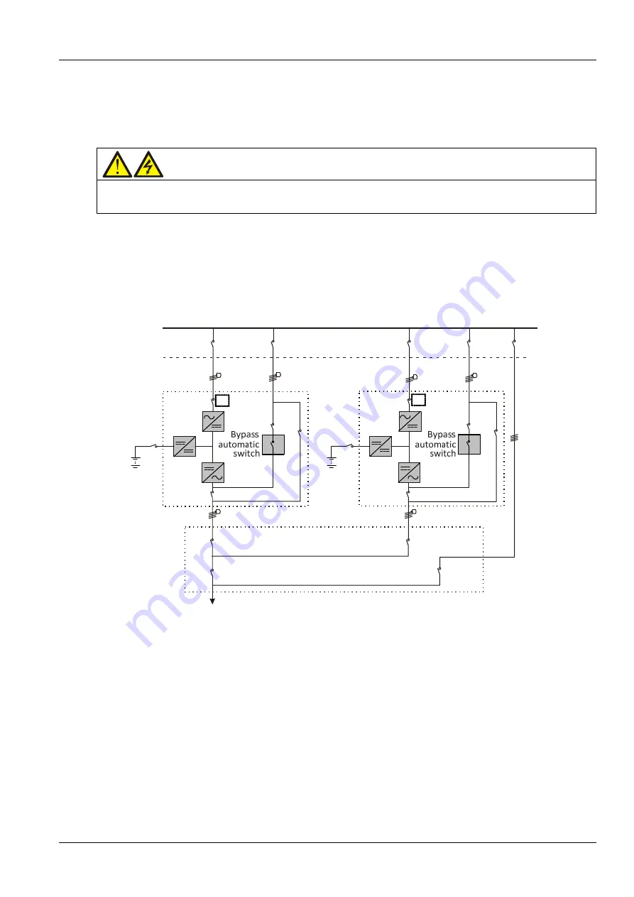
P lace the U PS m odules side by side and interconnect as show n in Fig ure 6 -1. T he output distribution m ode
(Q E 1, Q E 2 m ust be config ured) show n in Fig ure 6 -1 is recom m ended to facilitate m aintenance and system
testing .
Input
power
supply
Mains
input
L1,L2,L3,N
BCB
Battery
1
Rectifier
Charger
Inverter
Static
switch
Q1
Q5
QE1
QOP
L1,
L2,L3,N
Q3
Output
distribution
Q2
External
bypass
switch
Ex
te
rn
a
l
m
ai
n
te
na
nc
e
by
pa
ss
Mains
input
L1,L2,L3,N
BCB
Battery
2
Rectifier
Charger
Inverter
Static
switch
Q1
Q5
QE2
QBP
L1,
L2,L3,N
Q3
Q2
To
load
UPS
1
UPS
2
Figure 6-1 Schem atic of typical parallel system (w ith com m on in put, separate batteries an d output)


