C h apter 7 C om m un ication 77
L iebert E X S 30 kV A A n d 4 0 kV A U P S U ser M an ual
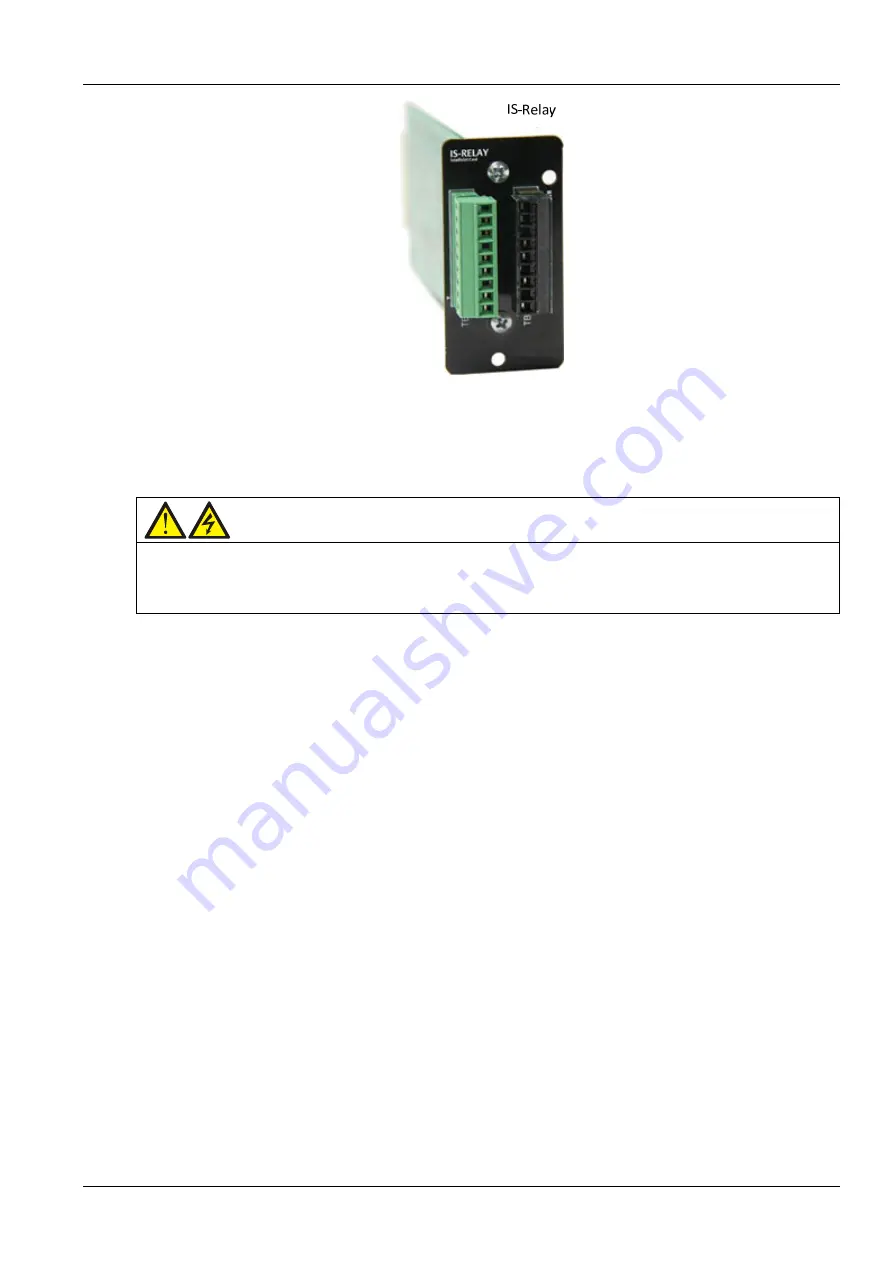
Figure 7-5
IS-R E L AY c ard
For m ore inform ation of the IS -R elay card, refer to the
Liebert IntelliSlot IS-R elay C ard U ser M anual
.
7.1.3
Installation P roced ures
W a rn in g
Som e electron com pon en ts in th e in tellig en t card are sen sitive to static, th erefore, do n ot touch th e electron
com pon en ts or circuit in th e intellig en t card by h an d or oth er con ductive m aterials, so as to protect th e in tellig en t
card ag ain st static sh ock. W h en rem ovin g or in stallin g th e in tellig en t card, hold th e card side edg e to operate it.
1. R em ove the protective cover on the U P S intelligent card, retain the screw s, and keep the protective cover
properly for future use.
2 . Insert the intellig ent card (along tw o side s of the Intellislot port) into the port position recom m ended in
F ig ure 7-1, and then fasten the screw s.
N ote:
1. S IC card, U N IT Y-D P card, U N IT Y-LIFE card, and IS -R E L AY card can be installed at Intellislot1 or Intellislot2 .
2 . W hen installing the U N IT Y-D P card or the U N IT Y-LIFE card at Intellislot1 or Intellislot2 , if you w ish to
chang e the baud rate, just chang e the ‘serial port 2 baudrate’ on the operator and display panel.
3. W hen installing the SIC card at Intellislot2 , if you w ish to change baud rate, just chang e the ‘serial port 2
baudrate’ on the operator and display panel.
4 . W hen installing the SIC card at Intellislot1, if you w ish to change the baud rate, you f irst need to conf irm
the current com m unication m ode of SIC card is R S 23 2 or R S 4 8 5 via the SIC card w eb interface. If R S 23 2
com m unication m ode, it can be realized by chang ing ‘serial port 1 baudrate’ on the operator and display
panel; if R S 4 8 5, it can be realized by chang ing ‘serial port 2 baudrate’ on the operator and display panel.
5. T he path of ‘serial port 1 baudrate’ and ‘serial port 2 baudrate’ on the operator and display panel is: m ain
m enu screen -> setting -> m onitor -> serial port 1 baudrate or serial port 2 baudrate.
6. T he path of m ain m enu screen -> setting -> m onitor ->U P S address is used to set the com m unication
address of this U P S through the Y D N 23 protocol.


