C o n fo rm ity a n d s ta n d a rd s
1. T h e U P S com plies w ith 20 14 /35/E U (L V D ), 20 14 /30 /E U (E M C ), 20 11/6 5/EU (R oh s) an d th e follow in g product
stan dards for U P S:
IE C /E N 6 20 4 0 -1, G en eral an d safety requirem en ts for U P S
IE C /E N 6 20 4 0 -2: C lass C 2 com plian t
IE C /E N 6 20 4 0 -3: P erform an ce requirem en ts an d test m eth ods
2. C on tin ued com plian ce requires in stallation in accordance w ith th ese in struction s an d th e use of m an ufacturer
approved accessories on ly.
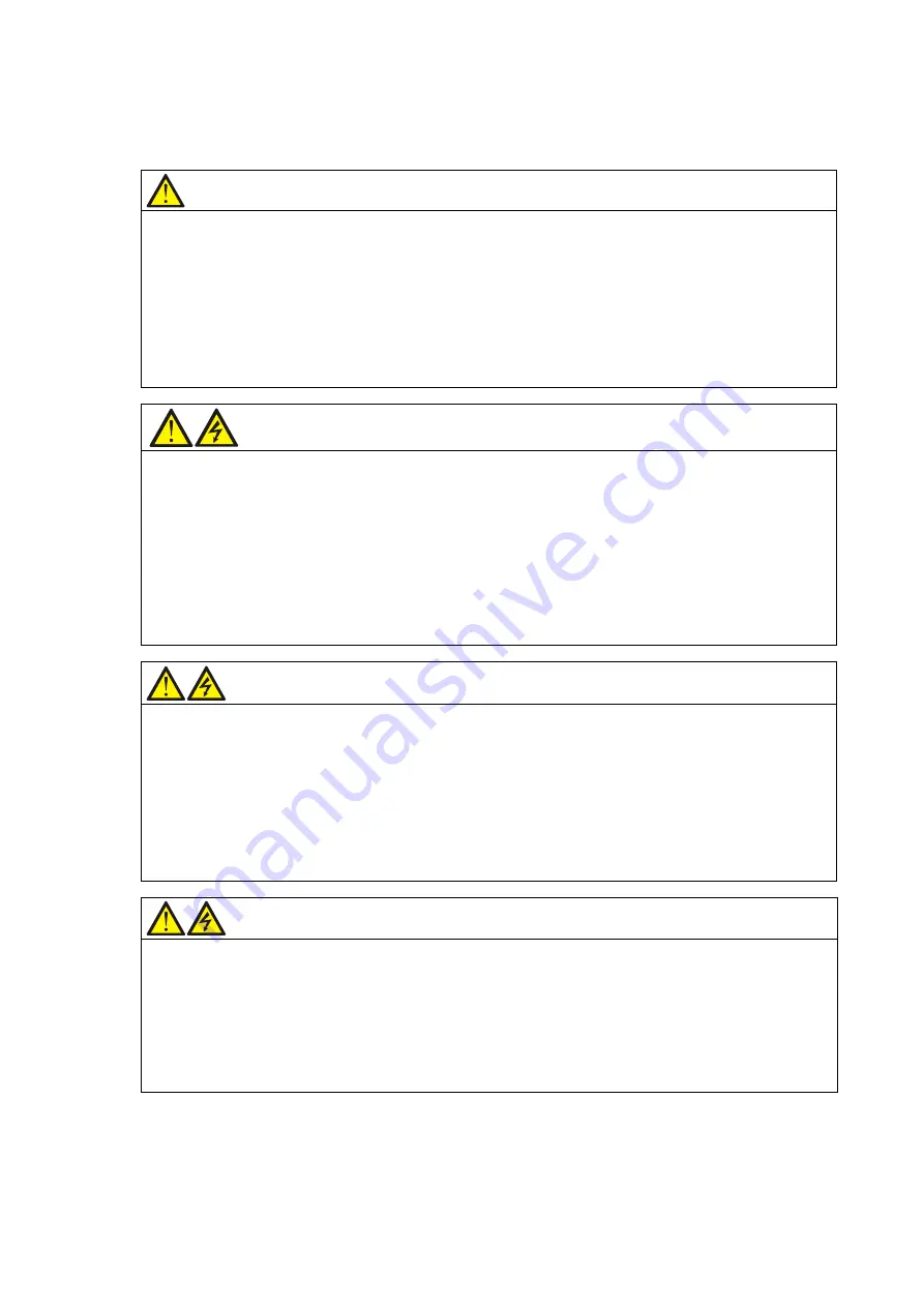
W a rn in g
1. B efore m oving or rew irin g the U P S, discon nect m ain s in put pow er an d th e battery an d m ake sure th at th e
U P S is com pletely sh ut dow n . O th erw ise, th e output term in al m ay carry live voltag e, presen tin g an electric
sh ock h azard.
2. L iquid or oth er irrelevan t extern al objects are proh ibited in side th e U P S.
3. In case of a fire, a dry ch em ical fire extin g uish er is essen tial. U sin g a foam fire extin g uish er w ill cause electric
sh ock.
4 . T o preven t th e radio frequ en cy of output cables from disturbin g oth er electric equipm en t, it is recom m en ded
to use th e U P S output cable w ith th e len g th less th an 10 m .
W a rn in g : h ig h e a rth le a k a g e c u rre n t
1. E arth con n ection is critical before con n ectin g th e in put su pply (in cludin g both m ain s supply an d battery).
2. E arth leakag e curren t is less th an 250 0 m A .
3. T ran sien t an d steady state earth leakag e curren ts, w h ich m ay occur w h en th e eq uipm en t is started, sh ould be
taken in to accoun t in th e selec tion of in stan tan eous R C C B s or R C D devices. R C C B w h ich is sen sitive to
un idirection al D C pulse (class A ) an d in sen sitive to tran sien t state curren t p ulse m ust be selected.
4 . N ote also th at th e earth leakag e curren ts of th e load w ill be carried by th e R C C B s or R C D s.
5. T h e equipm en t m ust b e earth ed in accordan ce w ith th e local electrical code of practice.
W a rn in g : b a c k fe e d in g p ro te c tio n
T h is U P S is fitted w ith a dry c on tact closure sig n al for use w ith an extern al autom atic discon n ect device
(supplied in d ep en den tly) to protect ag ain st backfeedin g voltag e in to th e in com in g term in al th roug h th e rectifier
or bypass sw itch circuit. A label m ust be add ed at all extern al in com ing prim ary supply disconnect device to
w arn service person n el th at th e circuit is conn ected to a U P S. T h e text of th e label h as th e follow in g m eanin g :
R isk of voltag e backfeed! Isolate th e U P S, th en ch eck for h azardous voltag e betw een all term in als in cluding th e
protective earth before w orkin g on th is circuit.


