Vertiv™ XTE 802G Generator Room Walk-In-Cabinet Description and Installation Manual
20
3
Sequence of Procedures
3.1
General
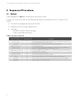
Perform the procedures in
(in the order listed) to fully install the XTE 802G.
Other practices and manufacturer’s documents will be required to complete the installation of the system. This includes, but is not
limited to:
•
OSP cable fishing, sealing, grounding, splicing, and termination.
•
Equipment manufacturer’s drawings and documentation.
•
Refer also to…
-
SD-2019014-01 (XTE 802G Schematic Drawings).
-
J-2019014-01 (XTE 802G Job Drawings)
Table 3-1:
Sequence of Procedures
Section in this Document
Starting on Page
Description
Provides information that will help the project engineer determine an appropriate use and location for
the XTE 802G, including associated foundation options.
Describes the front door and operation of the front door intrusion alarm switch.
Provides installation overview.
Describes the transportation and storage requirements, the safe handling of the XTE 802G, and the
procedures to install the XTE 802G and associated foundation options.
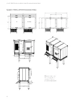
Provides an installation diagram to assemble the sheet metal frame furnished to fill in the gap between
the installed XTE 802 and XTE 802G.
Provides methods for sealing cable entries.
Describes the grounding requirements for the XTE 802G.
Provides DC wiring information for the interior DC lights and optional DC smoke detector.
Provides procedures for preparing the cable sheaths and routing the cables within the XTE 802G.
Describes the wiring for the XTE 802G alarms.

