Vertiv™ XTE 802G Generator Room Walk-In-Cabinet Description and Installation Manual
28
Alternative Installation Procedure #1 (6 Inch Auger)
1.
Using a 6 inch auger, drill to a depth of 5 to 7 feet while minimizing enlargement of the bore. Drill the pier into the hole using
the standard methodology and parameters.
2.
Fill and tamp any space around the top of the helical with dirt or small gravel.
Alternative Installation Procedure #2 (New Location)
In the event the base-plate is more than 11 inches above grade, due to subsurface conditions including bedrock, boulders and other
immovable objects;
1.
Consider changing the location several feet while maintaining the required minimum antenna separation requirements.
Follow the steps of appropriate procedures above.
NOTE!
If more than one helical is unable to be driven to the required depth, please consult Vertiv engineering. For
grounding purposes, NEC requires a minimum of 10 vertical feet of helical in the ground. Consult the NEC to determine if a
ground ring is required for your installation.
6.4
Combo Platform Installation
6.4.1
Combo Helical Platform Installation (P/N D1000-0010-0171)
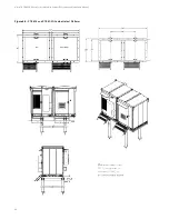
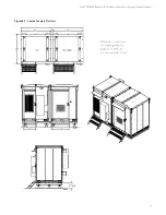
This platform is designed to be installed on helicals and it accommodates both the XTE 802 and XTE 802G. The default location for
the XTE 802G is to the right of the XTE 802 next to the ATS but the XTE 802G can be mounted on either side of the XTE 802 to
support any site layout. All conduits and cabling is installed at WWT so a completely configured platform can be installed at the site.
Simply install the helicals in the ground then lift and set the platform onto the helicals. See
Combo Helical Platform Installation Procedure
1.
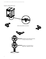
Assemble the universal driving tool on the correct Kelly bar adapter.
2.
Connect Kelly bar adapter to Kelly bar on the drive head.
3.
Move drive tool assembly to first helical and attach universal driving tool to helical plate paying attention to keeping the Kelly
bar as centered in the helical as possible. The leveling hardware can be used for this temporary attachment.
4.
Lift helical upright allowing it to swing free of the ground.
5.
Maneuver the helical directly over the installation point.
6.
Lower the helical until the point of the helical is forced into the ground on target.
7.
Screw helical 12 inches into the ground and plumb using a level on 2 sides 90 degrees from each other.
8.
Continue screwing the helical into the ground while correcting the Kelly bars orientation so the helical embeds itself straight.
A ground man can be of assistance in keeping the foundation plumb during the installation.
9.
Drive the helical until the top of the helical plate is 7 inches above grade. Stop the driving tool assembly. Disconnect the
universal driving tool from the helical plate.
10.
Repeat steps 3 through 9 for all helicals paying attention to helical plate orientations and to accomplish 74 inch and 86 inch
centers between all four helicals. See
11.
Install leveling hardware in each helical. Each helical has four sets of leveling hardware and each set of leveling hardware
consists of one threaded rod, four nuts, eight washers, and four lock washers. Leave the top washer, lock washer, and nut off
until platform is set.

