Vertiv™ XTE 802G Generator Room Walk-In-Cabinet Description and Installation Manual
46
9
Grounding the XTE 802G
9.1
Important Safety Instructions
DANGER!
Adhere to the “Important Safety Instructions” starting on page vi.
9.2
Safety Precautions
DANGER!
RISK OF ELECTRICAL SHOCK, GENERAL
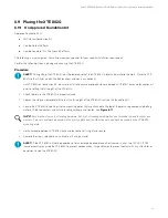
All XTE 802G grounding must be installed and verified prior to connecting any power cables (AC or DC) and turning-up of
the XTE 802G.
Ensure that all NEC (National Electric Code), CSA (Canadian Electric Code) and local codes for safety and wiring are followed.
Consideration for corporate standards also apply.
9.3
General
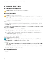
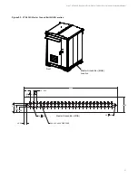
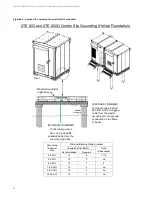
All external ground wires shall only be terminated to the Master Ground Bar (MGB) located at the base of the right side of the XTE
802G (see
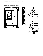
All internal ground wires shall be terminated to an interior ground bar prior to any externally derived electrical power being connected
to the XTE 802G (see
).
All XTE 802G grounding must be installed prior to turn up of XTE 802G.
•
The internal XTE 802G frame and all attached equipment are factory grounded to the XTE 802G interior ground bar.
•
A 2 AWG green conductor is factory connected from the XTE 802G interior ground bar to the Master Ground Bar (MGB)
located on the lower right exterior of the XTE 802G.
•
The XTE 802G structure is separately grounded to the Master Ground Bar (MGB).
9.4
Master Ground Bar (MGB)
ALERT!
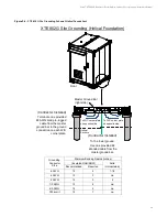
Grounding should be accomplished according to local practices and in accordance with the latest NEC codes.
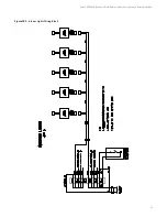
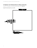
Refer to
, and
for XTE 802G site grounding schemes.
Procedure
1.
Connect one provided stranded cable from the Master Ground Bar (MGB) to site ground per local practices. Refer to
for location.
2.
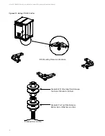
The Master Ground Bar (MGB) is configured to terminate 2-hole lugs, 3/8” hardware, on 1” center spacing (see
3.
Allow for a 0.125” minimum space between adjacent lugs.
9.5
Ground Bar (Interior)
See


