NOTE: When removing an EBC, the circuit breaker on the rear of the cabinet must be turned off before
disconnecting the cable.
NOTE: If the UPS will be shipped or stored for an extended time, the connector should be
disconnected. This will minimize any stand-by current drain on the batteries and help attain their
design life.
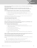
3.5.1 Installing the Optional Liebert IntelliSlot® Card and Communication Cables
1. On the GXT4, remove the protective cover of the Liebert IntelliSlot port and set it aside.
2. Insert the IntelliSlot card into the IntelliSlot port and secure it with screws.
3. To connect any cable associated with and IntelliSlot card, refer to the quick-installation guide
provided with the card.
To configure and use the Liebert IntelliSlot communication card, refer to the card’s user manual. Find
manuals online at http://www.VertivCo.com/en-us/support/.
3.6 Connecting Input/Output Power
The GXT4 ships with a power distribution box attached.
Refer to the following instructions for removal and installation.
NOTE: Do not operate the UPS with the power distribution box removed. To shut off all power to this
box and to the load, utility input power must be disconnected.
3.6.1 Installing the Power Distribution Box
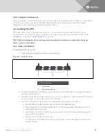
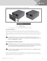
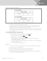
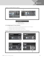
1. Align the connectors and press the power-distribution box onto the UPS.
2. Hold the box firmly against the UPS and tighten the captive screws except the one over the
maintenance bypass breaker.
3. Turn the output and input breakers "On."
4. Start the UPS according to start-up instructions.
5. Verify that the UPS lamp is illuminated.
6. Turn the maintenance bypass breaker "Off."
7. Insert the maintenance-bypass-interlock bracket behind the captive screw and tighten the
screw.
NOTE: The maintenance bypass breaker interlock bracket must be installed behind the captive screw,
and the screw must be tightened for the UPS to operate in inverter mode.
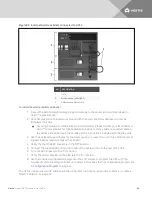
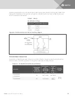
3.6.2 Electrical Connections for the Power-distribution Box
Electrical connections are made through a removable power distribution box that attaches to the rear of
the UPS.
•
PD2-CE6HDWRMBS fits the 5000 and 6000VA models of the Liebert GXT4
•
PD2-CE10HDWRMBS fits the 10,000VA model of the Liebert GXT4
The installer must provide an upstream branch circuit breaker. The input circuit breaker on the
distribution box and the output circuit breaker on the rear of the power distribution box disconnect all
power between the main cabinet and the distribution box.
Vertiv
| Liebert GXT4 Installer/User Guide |
25
Summary of Contents for GXT4-10000RT230
Page 1: ...Liebert GXT4 UPS 230 V 5000 VA 10 000 VA Installer User Guide...
Page 6: ...Vertiv Liebert GXT4 Installer User Guide 6...
Page 10: ...Vertiv Liebert GXT4 Installer User Guide 10 This page intentionally left blank...
Page 20: ...Vertiv Liebert GXT4 Installer User Guide 20 This page intentionally left blank...
Page 30: ...Vertiv Liebert GXT4 Installer User Guide 30 This page intentionally left blank...
Page 40: ...Vertiv Liebert GXT4 Installer User Guide 40 This page intentionally left blank...
Page 48: ...Vertiv Liebert GXT4 Installer User Guide 48 This page intentionally left blank...
Page 56: ...Vertiv Liebert GXT4 Installer User Guide 56 This page intentionally left blank...
Page 64: ...Vertiv Liebert GXT4 Installer User Guide 64 This page intentionally left blank...
Page 65: ......


