background image

Chapter  3    Electrical  Installation            21 

APM 300 Integrated UPS Single Module And Parallel System    User Manual


Rectifier input terminal

B

A amplified view

B amplified view

mA mB mC mN

bA bB bC

PE

Bypass input terminal

Output terminal

oA oB oC

oN

-

Battery input terminal

+

N

Switch cabinet

Main power cabinet

A

B

Switch cabinet

Main power cabinet

Rectifier input terminal

mA mBmC mN

bA bB bC

PE

Bypass input terminal

oA oB oC

oN

Output terminal

Battery input terminal

N +

-

A Amplified view

B Amplified view


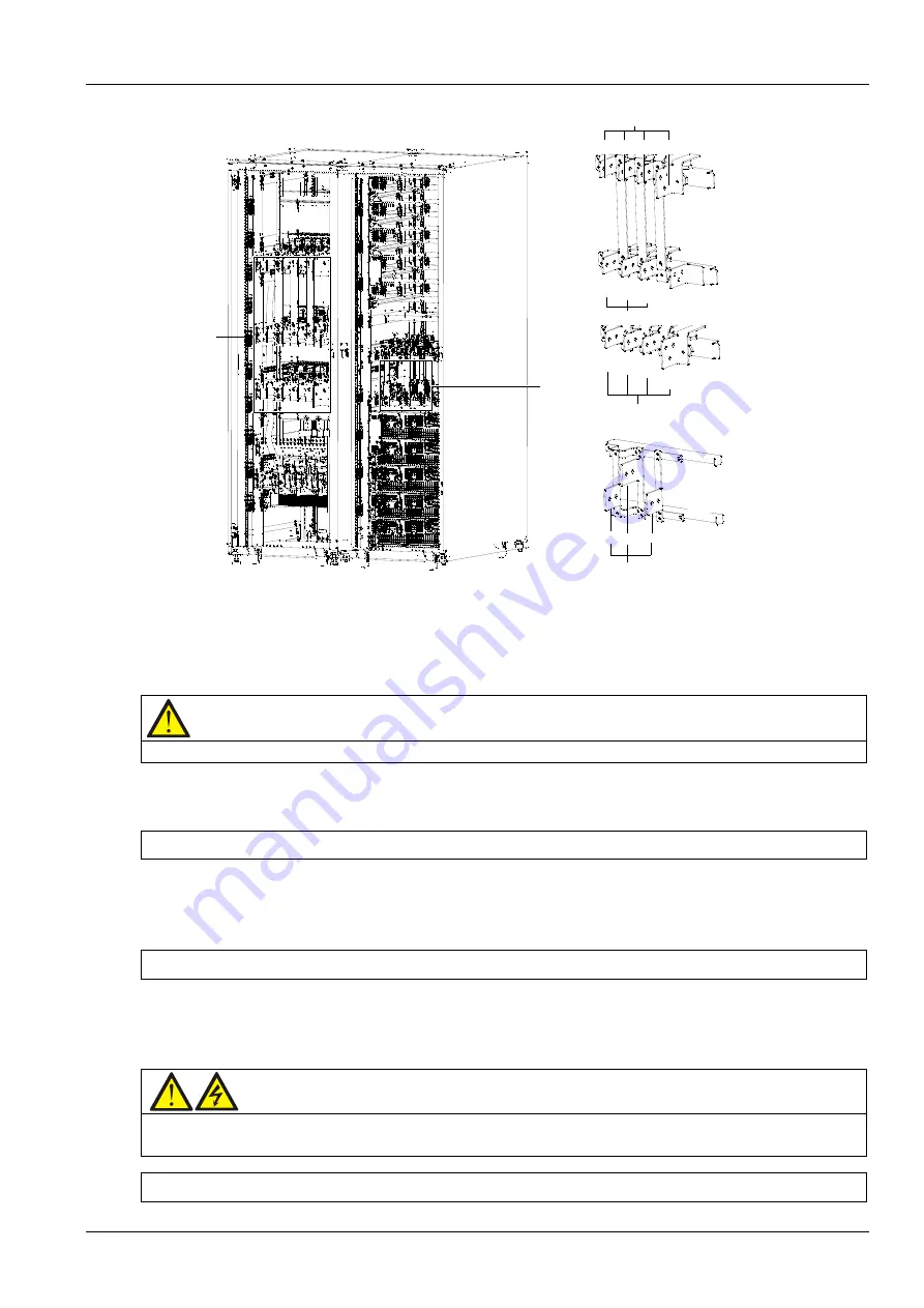
Figure 3-2


Connection terminals of power cables (back view) 

3. The UPS uses top cable entry and bottom cable entry. Remove the covers on the top or bottom of the 
switch cabinet and main power cabinet of the UPS according to your need.     
4. Connect the input earth cable to the PE terminal.     

Note 

The earth cable and neutral cable must be connected in accordance with local and national codes of practice.   


5. Identify and make power connections for the input cables according to one of the following two procedures, 
depending on the type of installation.   

Common input connection 

 
a) In common bypass and rectifier input configuration, use the accessory M12 screws to connect the AC input 
cables to the rectifier input terminals (mA-mB-mC-mN) or bypass input terminals (bA-bB-bC-mN), and tighten 
the connections to 50N.m. Ensure correct phase rotation.   

Split bypass connection 

 
b) In split bypass configuration, use the accessory M12 screws to connect the rectifier input cables to the 
rectifier input terminals (mA-mB-mC-mN), connect the bypass input cables to the bypass input terminals 
(bA-bB-bC-mN), and tighten the connections to 50N.m. Ensure correct phase rotation.   

Warning 

In split bypass configuration, remove the linking busbars between the bypass input and rectifier input. The rectifier 
input and bypass input must be referenced to the same neutral point.   


System output connection 


Summary of Contents for Liebert APM 300

Page 1: ......

Page 2: ......

Page 3: ...contact the nearest Emerson local sales office or service center Copyright 2011 by Emerson Network Power Co Ltd All rights reserved The contents in this document are subject to change without notice E...

Page 4: ...ct will be stored or remain de energized for a long period it must be placed in a dry and clean environment within specified temperature range 2 This product should be used in an appropriate operating...

Page 5: ...industrial use only and is not for use in any life support application Warning This is a Class C3 UPS product for commercial and industrial application in the second environment Installation restrict...

Page 6: ...parts All equipment maintenance and servicing procedures involving internal access requires the use of a tool and should be carried out only by trained professionals There are no user serviceable part...

Page 7: ...The Manual Covers The Following Equipment Product Model APM 300 Liebert APM 300...

Page 8: ...n Appendix 2 V1 2 October 10 2014 Change the address of Emerson Network Power Co Ltd add Frequency converter mode Dual bus LBS system mode and ECO mode in Section 1 5 change Figure 6 5 change the desc...

Page 9: ......

Page 10: ...Battery Protection Set By Commissioning Engineer 10 Chapter 2 Mechanical Installation 11 2 1 Notes 11 2 2 Preliminary Check 11 2 3 Environmental Requirements 11 2 3 1 UPS Location 11 2 3 2 Battery Lo...

Page 11: ...1 Start Screen 28 4 2 2 Primary Screen 28 4 2 3 Default Screen 29 4 3 Detailed Description Of Menu Items 30 4 4 PromptWindow 32 4 5 Alarm List 32 Chapter 5 Operating Instructions 37 5 1 Brief Introdu...

Page 12: ...t Installation 52 7 2 3 External Protective Device 53 7 2 4 Power Cable 53 7 2 5 Parallel Control Cable 53 7 2 6 Remote EPO 54 7 3 Operation Procedures For Parallel System 55 7 3 1 Startup Procedures...

Page 13: ...er to Bypass is allowed for service the bypass module 71 10 3 Replacement Procedures Of Air Filter 72 10 4 Maintenance Of UPS And Options 72 Chapter 11 Specifications 73 11 1 Conformity And Standards...

Page 14: ...al voltage and frequency controller Improve noise rejection Due to the application of AC DC AC conversion mode the noise in the input power is effectively filtered and the load gets clean power supply...

Page 15: ...ctifier input switch Rectifier Maintenance bypass switch Bypass input switch Battery Battery charger Inverter Static switch Automatic inverter switch Maintenance bypass Output switch UPS output Figure...

Page 16: ...alarm messages Mains recovery When the mains resumes normal within allowable time the rectifier will start automatically at this time its output power will increase gradually and supply the load and...

Page 17: ...gulated mains supply to the loads The maintenance bypass can be manually selected through the maintenance bypass switch and it can be disconnected by turning the switch to OFF Warning The internal mai...

Page 18: ...s supply L1 L2 L3 N Charger Rectifier Inverter STS UPS 2 output distribution unit 0 2 pcs L1 L2 L3 N L1 L2 L3 N UPS 1 output distribution unit 0 2 pcs UPS 1 output distribution UPS 2 output distributi...

Page 19: ...ntenance mode manual bypass ECO mode Parallel and redundancy mode Dormancy mode Common battery mode Frequency converter mode Dual bus LBS system mode Normal mode As shown in Figure 1 5 the UPS rectifi...

Page 20: ...ad from the inverters to the bypass source with no interruption in power to the load Should the inverters be asynchronous with the bypass the static switch will perform a transfer of the load from the...

Page 21: ...ter 5 Operating Instructions except that the load is normally on the bypass mains the Inverter LED is normally off and the corresponding alarm message Bypass mode will appear on the LCD Warning In ECO...

Page 22: ...ge The boost charge voltage can be set as required by the type of battery For VRLA batteries the maximum boost charge voltage should not exceed 2 4V cell 3 Float charge The float charge voltage can be...

Page 23: ...ion must be used together with the Emerson battery temperature detection device a standard option 1 7 Battery Protection Set By Commissioning Engineer Battery low pre warning The battery low pre warni...

Page 24: ...suitable for connection to 3 phase 5 wire A B C N PE TN and TT AC power distribution systems IEC60364 3 Warning battery danger Take special care when installing batteries When connecting batteries the...

Page 25: ...ery room meets the EN50272 2001 requirement Batteries should be mounted in an environment where the temperature is consistent and even over the whole battery Temperature is a major factor in determini...

Page 26: ...short distances by its casters 2 4 2 Clearances The UPS has no ventilation grilles at either side therefore no clearance is required at either side The component layout of the UPS supports front acces...

Page 27: ...e shipped separately and should be connected mechanically at site The connection procedures are as follows 1 Place the main power cabinet and switch cabinet closely side by side with the main power ca...

Page 28: ...de Screw hole for cabinet connection Beam Right side Figure 2 2 Screw holes for cabinet connection onmain power cabinet 2 5 3 Installing Power Module The installation positions of the power modules ar...

Page 29: ...P switch setting method DIP switch setting Module address 1 2 3 4 5 6 7 8 9 10 2 Place the ready switch on the front panel of the module to the up position that is in unready state 3 Remove the dummy...

Page 30: ...requirement of rated input current including the rated battery charge current see Table 3 1 UPS bypass and output cables The size of the UPS bypass and output cable differs with the UPS power rating...

Page 31: ...voltage drop of 4Vdc is permissible at the current ratings given in Table 3 1 To minimize the formation of electromagnetic interference do not form coils 3 The connection terminals are shown in Figure...

Page 32: ...ified upstream of the input distribution panel 3 Battery A battery protective device for example a fuse or a breaker must be fitted to provide overcurrent protection for the 4 The rated voltage of the...

Page 33: ...2 oC 2 oN 2 A Amplified view connection terminals in main power cabinet Figure 3 1 Connecting parallel power cables 3 1 9 Connecting External Power Cables Important The operations described in this se...

Page 34: ...onnected in accordance with local and national codes of practice 5 Identify and make power connections for the input cables according to one of the following two procedures depending on the type of in...

Page 35: ...nnect these links or close the BCB before authorized by the commissioning engineer 8 Replace the covers removed in step 3 and close the back doors of the cabinets Note After connection take appropriat...

Page 36: ...re detection J8 4 GND Power ground 1 The default function of J7 1 is battery room environment detection then generator connected must be configured by configuration software before becoming active Whe...

Page 37: ...intenance bypass switch state Connect to J9 4 The auxiliary contact requirement for the external maintenance bypass switch is as follows When the switch is open the external bypass auxiliary contact i...

Page 38: ...f J10 are shorted or pins 2 and 1 of J10 are opened If an external EPO facility is required pins 1 and 2 or 3 and 4 of J10 are reserved for this function The external EPO facility is also connected to...

Page 39: ...nel is divided into three functional areas mimic power flow chart LCD display with menu keys control keys as shown in Figure 4 1 The components of the operator control and display panel are described...

Page 40: ...de Solid red Inverter fault Off Inverters not operating Load indicator Solid green UPS output on and normal Solid red UPS output on and overloaded Off UP output off Status indicator Solid green Normal...

Page 41: ...dly and menu driven LCD allows you to easily browse through the input output load and battery parameters of the UPS learn current UPS status and alarm information perform functional setting and contro...

Page 42: ...window as appropriate From any menu on the primary screen pressing the F1 key returns to the OutPut menu and pressing the F3 F4 keys enters the screen displayed in Figure 4 4 where you can select the...

Page 43: ...rmat Menu window and data window The menu window provides the menus of the data window The data window displays the items of the menu selected in the menu window UPS parameters can be browsed and func...

Page 44: ...age option Provides 12 optional LCD languages Settings Display contrast Adjusts the LCD contrast Date format set Three formats selectable MM DD YYYY DD MM YYYY YYYY MM DD Date time Sets the date and t...

Page 45: ...rtain conditions or to require your confirmation of a command The prompts are provided in Table 4 8 Table 4 8 Prompts and meanings Prompt Meaning Transfer with interrupt confirm or cancel The inverter...

Page 46: ...tifier shutdown and battery discharging Rectifier Overtemp The temperature of the heatsink is too high to keep the rectifier running The UPS can recover from this fault automatically Check the environ...

Page 47: ...displayed value is correct 3 If yes disconnect the non critical load In a parallel system this alarm will be triggered if the load is severely unbalanced SystemOver load This alarm appears when the t...

Page 48: ...of Emerson to inspect the battery installation Manual Turn On INVERTER ON key activated on the operator control and display panel to turn on the inverter Manual Turn Off INVERTER OFF key activated on...

Page 49: ...ic module Seek technical assistance from the local customer service center of Emerson SPM Branch Curr Over LL Load too large exceeding route current low threshold set by commissioning engineer 60 of r...

Page 50: ...the operating steps refer to Chapter 4 Operator Control And Display Panel 2 During operation the buzzer alarm may occur at any time Press SILENCE ON OFF key to silence the audible alarm 3 When UPS us...

Page 51: ...the load is not ready to receive power open the corresponding output distribution switch The procedures for turning on the UPS from a fully powered down condition are as follows In a parallel system...

Page 52: ...dicator Green Status indicator Green 5 2 2 Start Up Procedures Into Battery Mode Battery Cold Start Note Only one power module is allowed in the main power cabinet before battery cold start 1 Verify t...

Page 53: ...the UPS transfers to normal mode 5 3 4 Transfer From Normal Mode To Maintenance Mode When the UPS is operating in normal mode use the following procedures to transfer the load from the inverter outpu...

Page 54: ...ter than 5 of rated UPS capacity and must be stable for battery maintenance test The load must be between 20 and 80 of rated UPS capacity and must be stable for battery capacity test The battery must...

Page 55: ...tion by selecting Stop testing on the Command menu 5 6 UPS Shutdown Procedures 5 6 1 Procedures For Completely Powering Down UPS Caution The following procedures will switch off all power to the load...

Page 56: ...ops charging or discharging If the mains input is present the UPS control circuit will remain active however the output will be turned off To remove all power from the UPS the rectifier input switch b...

Page 57: ...the OutPut menu press the F3 or F4 left or right key as needed to select the Language menu 2 Press the F5 enter key to move the cursor to the data window on the screen 3 Use the F3 or F4 up or down k...

Page 58: ...es shall be installed inside a key lockable cabinet or in a purpose designed dedicated battery room so that they are segregated from all but qualified maintenance personnel During battery maintenance...

Page 59: ...ed wet cloth To avoid any static or arcing do not use dry cloth or duster to clean the battery Do not use the organic solvent such as thinner gasoline volatile oil to clean the battery Otherwise the b...

Page 60: ...lled side by side on a solid floor these cables can be led into the UPS cabinet through the cable entry holes on the lower part of the battery cabinet 2 When multiple battery strings are used they sha...

Page 61: ...urrent at full load A 84 168 252 336 420 504 588 672 756 840 Reference rated current of BCB A 100 200 260 350 450 550 600 700 800 850 40 cell battery Max battery discharge current at full load A 80 16...

Page 62: ...onnections between battery BCB and UPS 3 wires at battery side battery consisting of 30 to 34 cells N N UPS N N UPS Figure 6 4 Connections between battery BCB and UPS 3 wire at battery side battery co...

Page 63: ...ttery terminals for loose connection If there is any loose screw tighten it immediately 2 Check that all safety devices are present and that their functions are normal Check that the battery managemen...

Page 64: ...regulations the disused lead acid storage battery must be recycled and shall not be disposed of with other methods Random discard or any other improper disposal of the disused lead acid storage batter...

Page 65: ...arallel system The installation of a parallel UPS should follow the installation procedure for a single UPS module with the additional requirements detailed in this section 7 2 1 Preliminary Checks Be...

Page 66: ...e protective device the current leakage protective device must be fitted upstream of the common neutral sinking point Note The lengths and specifications of the power cables of each UPS module includi...

Page 67: ...ovided on the operator control and display panel of each UPS module for controlling the EPO of each module respectively the parallel system also provides remote EPO function for controlling all UPS mo...

Page 68: ...nd only after finishing this operation step of each UPS module the next step can be carried on 7 3 1 Startup Procedures In Normal Mode These procedures are applicable to start the UPS under total powe...

Page 69: ...the inverter 3 Open the output switch of the UPS 4 Wait for 10 minutes before carrying out UPS maintenance or repair Warning hazardous battery voltage The UPS battery and connecting terminals remain e...

Page 70: ...itches isolating switches and breakers are disconnected and then UPS no longer supplies power to the load Caution The following procedures will cut off the load power making the load completely power...

Page 71: ...same neutral potential and the input earth leakage monitoring devices if installed must be located upstream of the common neutral sinking point 7 4 4 Control Cable For a dual bus system composed of t...

Page 72: ...e And Parallel System User Manual UPS 1 Bypass module LBS cable J2 J3 J4 J2 J3 J4 Bypass module UPS 2 LBS cable UPS 1 UPS 2 Bypass module Bypass module J2 J2 J3 J3 J4 J4 LBS cable LBS cable Figure 7 8...

Page 73: ...ble 5m 10m 15m 5m cable 04118683 10m cable 04118684 15m cable 04118685 Two cables should be selected to achieve redundancy 9 Parallel control cable 5m 10m 15m 5m cable 04118683 10m cable 04118684 15m...

Page 74: ...the rectifier input bypass input battery input and output load of the UPS 2 Wait five minutes for the internal DC bus capacitors of the UPS to fully discharge 3 Open the back door and remove the right...

Page 75: ...Cable connection 2 Replace the right side panel and close the back door of the UPS 3 Connect the rectifier input bypass input battery input and output load of the UPS Maintenance 1 Keep the connection...

Page 76: ...cleaning and replacement in dusty or other bad environment Frequent inspection or replacement should also be made in newly built construction The replacement method of the air filter is shown in 10 3...

Page 77: ...tor provides dry contact signal input and output The pins of the DB25 connector are described in Table 8 2 Table 8 2 DB25 connector pin description Pin No Pin name Description Pin 1 Va power output 9...

Page 78: ...ry commissioning Pin 13 GND common GND Power GND dry contact signal input common GND Others NC Cable options Emerson provides three cable options to connect the DB25 connector of the relay card to sui...

Page 79: ...switch Its factory default setting is shown in Figure 8 8 1 2 3 4 5 6 7 8 ON OFF Figure 8 8 Factory default setting of the DIP switch Bits 1 through 7 are designed for use in factory the user is not...

Page 80: ...us Verify that the relay card is properly inserted into the Intellislot port 2 The UPS does not respond to the UPS turn on dry contact input signal Verify that bit 8 of the DIP switch of the relay car...

Page 81: ...S status Action to take Ensure that the UF RS485 card is properly inserted into the Intellislot port and the cable is properly connected 8 2 7 Modbus Card The Modbus card can realize the conversion fr...

Page 82: ...tor your intelligent equipment and equipment room environment through the TCP IP interface provided by the SIC card For the installation and setting information of the SIC card refer to the Site Inter...

Page 83: ...ter 3 To ensure safety before servicing the power modules and bypass module be sure to use a multimeter to verify that the DC bus capacitor voltage is lower than 60Vdc and that the voltages between th...

Page 84: ...ore the connection of the cables disconnected in step 5 Note It requires massive force to push the bypass module into and pull it out of the cabinet To pull it out of the cabinet move it left and righ...

Page 85: ...the superior or subordinate switch to ensure cutting off the import or export when the current is too large Maintenance staff should be familiar with the typical ambient conditions where UPS is workin...

Page 86: ...munity IEC EN AS61000 series and construction IEC EN AS60146 series and 60529 11 2 Environmental Characteristics Table 11 2 Environmental characteristics Item Unit Rated power kVA 30 60 90 120 150 180...

Page 87: ...3 EN50091 3 at rated load and input voltage is 400V battery charging at maximum rated power 11 5 Electrical Characteristics Intermediate DC Circuit Table 11 5 Battery Item Unit Rated power kVA 30 60 9...

Page 88: ...neutral reference to the bypass neutral Frequency2 Hz 50 60 Overload 110 for 60min 125 for 10min 150 for 1min 150 for 200ms Fault current 340 current limitation for 200ms Non linear load capability3...

Page 89: ...10 Synchronisation window Hz 10 1 Default nominal voltage set at 400V at factory but can be changed to 380V or 415V by commissioning engineer at site 2 Bypass protected by upstream air breaker only by...

Page 90: ...signal processor EMC Electromagnetic compatibility EMI Electromagnetic interference EOD End of discharge EPO Emergency power off LBS Load bus synchronizer LCD Liquid crystal display MCCB Moulded case...

Page 91: ...witch Semiconductors Battery when applicable Insulation monitoring device when applicable This table is made following the regulation of SJ T 11364 Means the content of the hazardous substances in all...

Page 92: ...demarks of Vertiv Co All other names and logos referred to are trade names trademarks or registered trademarks of their respective owners While every precaution has been taken to ensure accuracy and c...

Reviews: