15
User Manual 10H52258UM60 - Rev. 3 - 01/2019
Mechanical Installation
APM 400/600
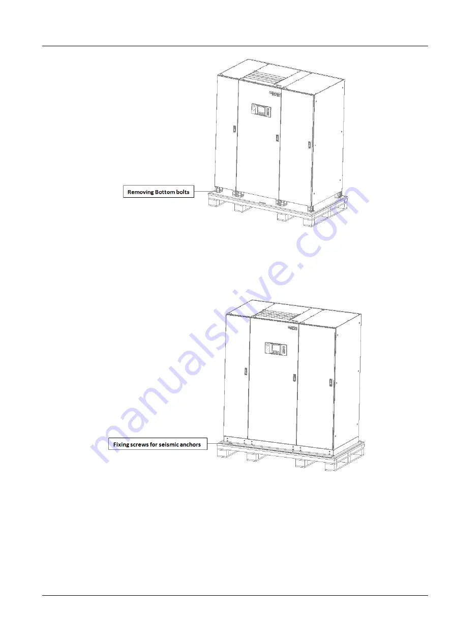
Figure 3-4 Removing the bottom fixing bolts
4.
If the cabinet is equipped with seismic anchors, they must be removed. The unit is normally fitted with 8 of
these anchors at the front and rear. Once these anchors have been removed, use the forklift to transfer the cabinet to
its installation position.
Figure 3-5 shows the seismic anchors fastened to the UPS system:
Figure 3-5 Seismic anchors on the UPS system
3.4
Initial Inspection
Ensure that the site has been prepared so that the UPS is installed in an environment that conforms to the
requirements as defined in the product technical specifications.
The previous section covers the UPS and battery unpacking procedures; the equipment should be unpacked under
the guidance of the authorized service personnel and trained engineers.
The final step in the initial check-up is to verify the UPS label and ascertain if everything is in place. To confirm that
the UPS complete and correct, refer to the UPS label attached to the inside of the front door, which indicates the
model, capacity and main parameters of the unit.
Once the initial check-up is complete, the complete UPS system may be inspected. The UPS system includes a
400kVA main power cabinet, another 200kVA power cabinet, and a switch cabinet (including the bypass control
module and bypass power module). It is fitted with a standard maintenance switch and may also be fitted with options


