User Manual 10H52258UM60 - Rev. 3 - 01/2019
30
APM 400/600
Electrical Installation & Connections
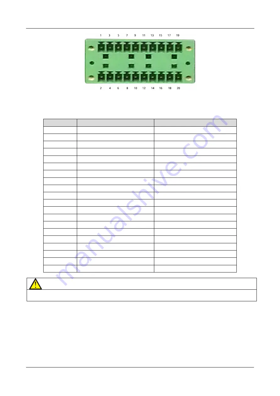
Figure 4-7 Dry Contact Port J22
See Table 4.5. for a pin-out description of Port J22
Table 4.5
Pin
Name
Description
1
12V_DRV
BCB driver signal
2
NC
Reserved
3
BCB STATUS
BCB state signal
4
NC
Reserved
5
GND_DRY
Dry ground
6
NC
Reserved
7
BCB_ONLine
BCB on line signal
8
NC
Reserved
9
NC
Reserved
10
NC
Reserved
11
GND_DRY
Dry ground
12
NC
Reserved
13
TMP_BAT
External battery temperature
14
NC
Reserved
15
12V_DRY
Power
16
NC
Reserved
17
GND_DRY
Dry ground
18
NC
Reserved
19
BAT_Ground_FAULT
Battery ground fault
20
NC
Reserved
Note
The BCB drive signal and external battery temperature signal cables must be shielded. Both ends of the
shielding sheath must be connected securely to the casing.


