33
User Manual 10H52258UM60 - Rev. 3 - 01/2019
Electrical Installation & Connections
APM 400/600
2
+ 12V
EPO activated when open circuit between this pin and Pin
1
3
+ 12V
EPO activated when shorted to Pin 4
4
EPO-NO
EPO activated when shorted to Pin 3
The EPO is triggered when pins 3 and 4 on J2 are shorted together, and when there is an open circuit between
the pins 2 and 1 on J2. If the UPS is fitted with a remote EPO contact, pins 1 and 2 or 3 and 4 are reserved for this
function. The external EPO facility is also connected to normally open or normally closed remote EPO switch
between these 2 terminals, using shielded cables. If this specific function is not required, there must be an open
circuit between pins 1 and 2 on J2, while the pins 3 and 4 on J2 must be shorted
Note
When the UPS EPO is triggered it shuts down the rectifier, inverter, and static bypass but does not disconnect
the input mains power internally. To disconnect all power to the UPS, open the external power switch, bypass
input switch, output switch, and BCB after the EPO as been triggered
4.2.7
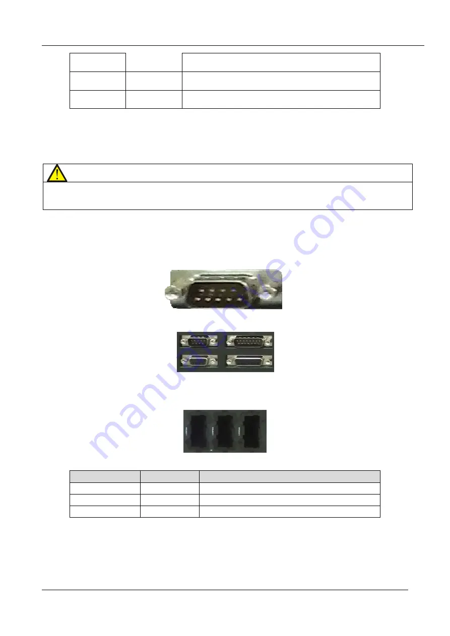
RS232 Communication Port
See Figure 4-5 for the position of the RS232 communication port. This port can be used to monitor and set-up
parameters when connected to a computer.
The RS232 port communication port provides serial data and is intended for use by authorized commissioning
and service personnel when commissioning and servicing the UPS.
4.2.8
Parallel and LBS Communication Port
See Figure 4-5 for the position and location of these ports.
4.2.9
Intellislot Port
The Intellislot ports are used for installing optional cards, such as the IS-UNITY-DP and IS-RELAY cards. Table
4.9 provides information about these optional cards, and their respective positions. For more detailed installation
procedures, refer to the specific content in the Optional Components of this manual.
Table 4.9
Optional Card
Model
Installation Position
IS-UNITY-DP card
IS-UNITY-DP
Intellislot ports 1 ~ 3 (port 1 or 2 recommended)
IS-Relay card
IS-RELAY
Intellislot port 1
•
The Intellislot port 2 shares communication resources with the RS 485 port. To avoid conflict, it is
recommended that the Intellislot port 2 not be used while using the RS 485 port for service and commissioning
activities.
•
The Intellislot port 3 shares communication resources with the RS232 port. To avoid conflict, it is
recommended that the Intellislot port 3 not be used while using the RS232 port for service and commissioning
activities.


