35
User Manual 10H52258UM60 - Rev. 3 - 01/2019
Operation Control and Display
APM 400/600
5
Operator Control and Display Panel
This section deals with the functions and features of the UPS Operator Control and Display Panel. The LCD
display information includes content such as the LCD screen types, detailed menu messages, prompt windows,
dialog boxes, and UPS alarm list.
5.1
Introduction
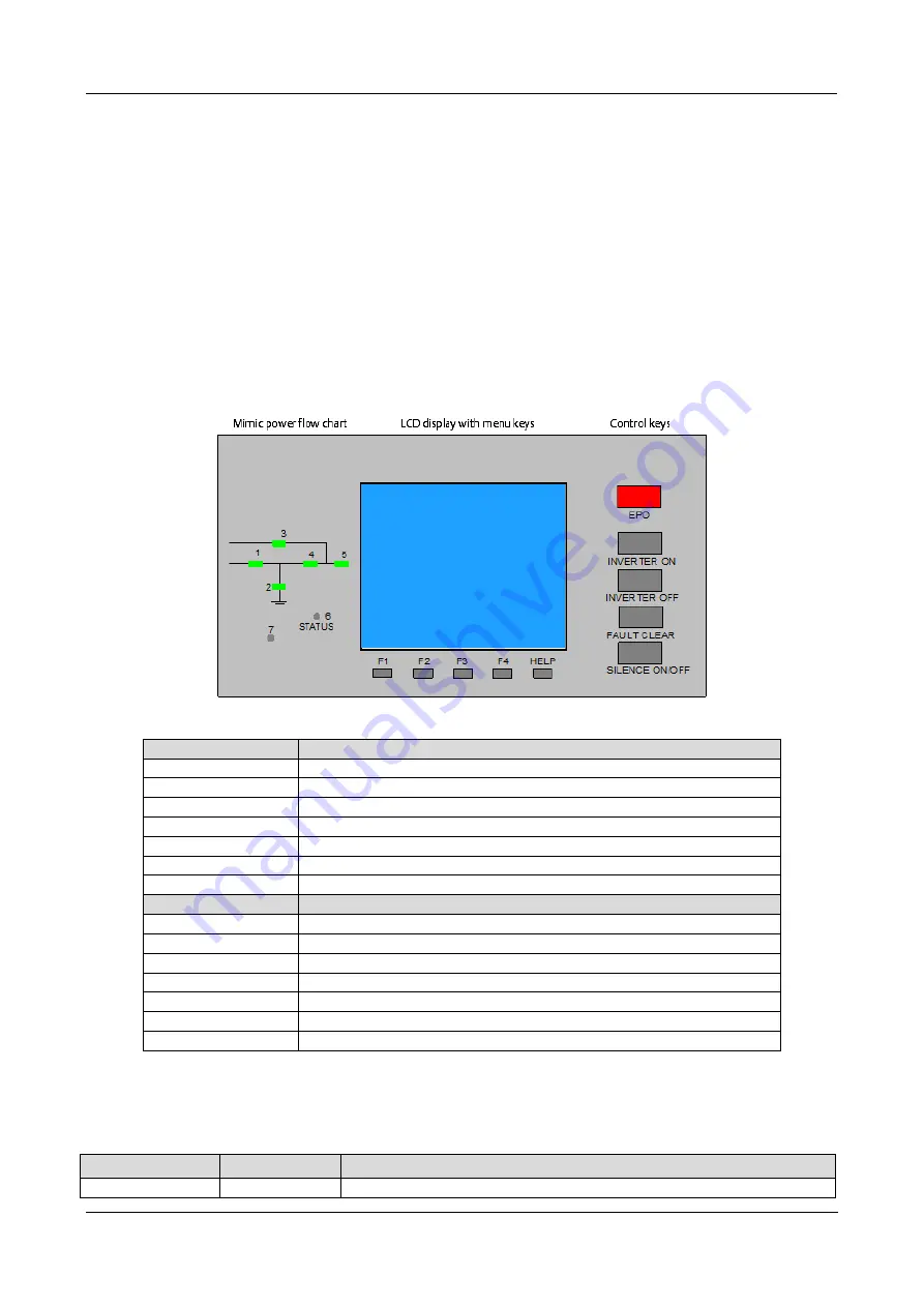
The Operator Control and Display Panel screen is located on the front of the UPS. It is designed to permit the
Operator to control and query the various measurement parameters, UPS, and battery alarms (in addition to the
battery status).
The panel is divided into 3 main areas:
•
Power flow chart
•
LCD display with menu keys
•
Control keys
Figure 5-1 illustrates the power flow chart, LCD display with the menu keys, and the control keys. For a
description of the various functions, see Table 5.1 below.
Figure 5-1 Operator Control and Display panel
Table 5.1
No.
Function
1
Rectifier Indicator
2
Battery Indicator
3
Bypass Indicator
4
Inverter Indicator
5
Output Indicator
6
Status Indicator
7
Buzzer
Key
Function
F1 to F4
LCD Menu Keys
HELP
LCD Menu Keys
EPO
EPO Switch
Inverter ON
Inverter Start Switch
Inverter OFF
Inverter Shutdown Switch
Fault Clear
Fault reset switch
Silence ON/OFF
Alarm Silencing Switch
5.2
LED Indicators
The LED indicators mounted on the power flow chart represent the different power paths and the current
operational status of the UPS. The table in Table 5.2 explains the indicators, state, and description of the various
indicators.
Table 5.2
Indicator
State
Description
Rectifier indicator
Solid green
The Rectifier is operating normally.


