User Manual 10H52258UM60 - Rev. 3 - 01/2019
52
APM 400/600
Introducing UPS Operations
Maintenance mode
If it is necessary to carry out any maintenance work on the UPS or service it, use the manual maintenance bypass
switch to transfer the load to the maintenance bypass, without interrupting the power supply to the load. All UPS
modules are fitted with a maintenance bypass switch, which is rated for the full load of a single module.
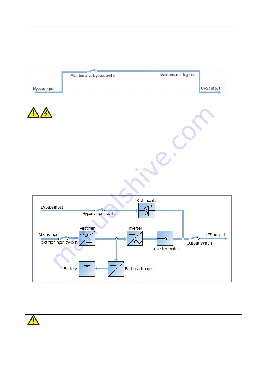
The block diagram in Figure 6-6 illustrates maintenance mode:
Figure 6-6 Maintenance mode block diagram
Warning
When the UPS is in maintenance bypass mode, the power modules and bypass module are inoperative and the
LCD is deactivated, and, while the output terminals corresponding to closed output distribution switches and the
neutral bars are energized, only the green indicator of the input SPD indicates that the UPS is connected to the
mains input.
ECO mode
In ECO mode, all the power switches and battery switches are closed, except for the maintenance bypass switch
and the system prioritizes the bypass as the preferred source for the load power in order save energy. When the
bypass supply frequency and voltage are within the normal operating limits (adjustable), the load is powered by
the bypass, while the inverter remains on stand-by; whereas whenever the bypass supply voltage/frequency are
outside limits, the system transfers the load to the inverter output. In this mode, the system can charge the
battery as normal.
The block diagram in Figure 6-7 illustrates ECO mode:
Figure 6-7 ECO mode block diagram
In order to set-up ECO mode, adjust the corresponding parameters via the operator control and display panel.
The start-up of the ECO mode is explained later in this chapter.
However, in normal mode, the load is powered by the bypass and the inverter indicator flashes, while LCD
indicates Bypass mode.
Note
In the ECO mode, the load is not protected against mains distortion.
Frequency converter mode


