User Manual 10H52258UM60 - Rev. 3 - 01/2019
54
APM 400/600
Introducing UPS Operations
No user-serviceable parts are located behind covers that require the use of a tool for removal. Only qualified
service personnel are authorized to remove such covers.
6.2
Power Switch
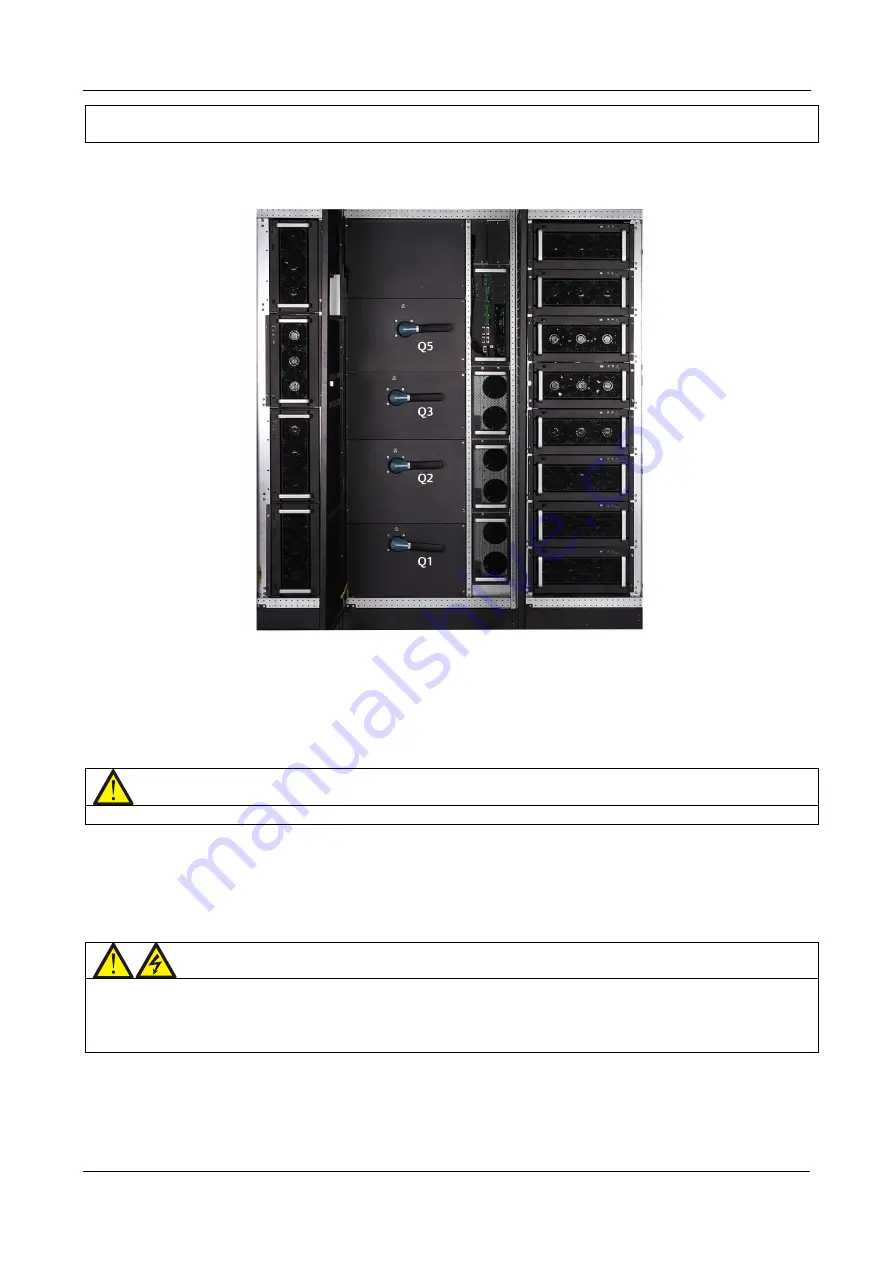
To access the UPS power switches, open the middle cabinet door.
Figure 6-8 illustrates the position of the power switches:
Figure 6-8 APM 400/600 Modular UPS power switches
The switches Q1, Q2, Q3, and Q5 are assigned the following functions:
•
Q1:- Rectifier Input switch - connects the UPS to the mains power supply.
•
Q2:- Bypass Input switch - connects the UPS to the bypass power supply.
•
Q3:- Maintenance Bypass switch - supplies power to the load in maintenance mode.
•
Q5:- Output switch - connects the UPS output to the load.
Note
The switch Q3 is fitted as standard, whereas Q1, Q2, and Q5 are optional.
6.3
UPS Start-up Procedure
The UPS must be installed completely and tested by an authorized engineer or personnel. Initially, the external
power supply switch should be closed, after which the UPS may be started.
6.3.1
Start-up in Normal mode
This section provides a detailed description of the start-up process in Normal operating Mode.
Warning
Prior to the Start-up process, remember that the start-up procedures result in mains voltage being present at
the UPS output terminals. If any load equipment is connected to the UPS output terminals, check with the users
if it is safe to apply power. However, if the load equipment is not ready to receive power, disconnect the
downstream load switch and attach a warning label on the connection point to the load.
The following are step-by-step instructions explaining how to switch the UPS on from the fully de-energized
condition:
•
Open the front door of the UPS. Check and confirm that the internal maintenance bypass switch Q3 is
disconnected. Ensure that the input cables and copper bars are connected correctly.


