71
User Manual 10H52258UM60 - Rev. 3 - 01/2019
Parallel System and LBS System
APM 400/600
8.2.3
External Protection Device
Warning
1. High earth leakage current: Always connect the system to earth before connecting the input supplies (mains
supply and battery).
2. The equipment must be earthed in accordance with the local electrical code of practice.
Refer to
3.1.9 External Protection Device
.
8.2.4
Power Cable
The power cable wiring is similar to that of the UPS module. Refer to 3.1 Power Cable Wiring.
The bypass and rectifier input supplies must use the same neutral line input terminal. If the input has a current
leakage protective device, it must be fitted upstream of the neutral line input terminal.
Note
1. The power cables (including the bypass input cables and UPS output cables) connected to each UPS module
should the same length and have the same specifications in order to facilitate load sharing.
2. The UPS can be used in common input or split bypass configuration. If the mains input and bypass input
come are derived from two separate transformers, then these two transformers should be connected to the
same earth network.
8.2.5
Parallel Cables
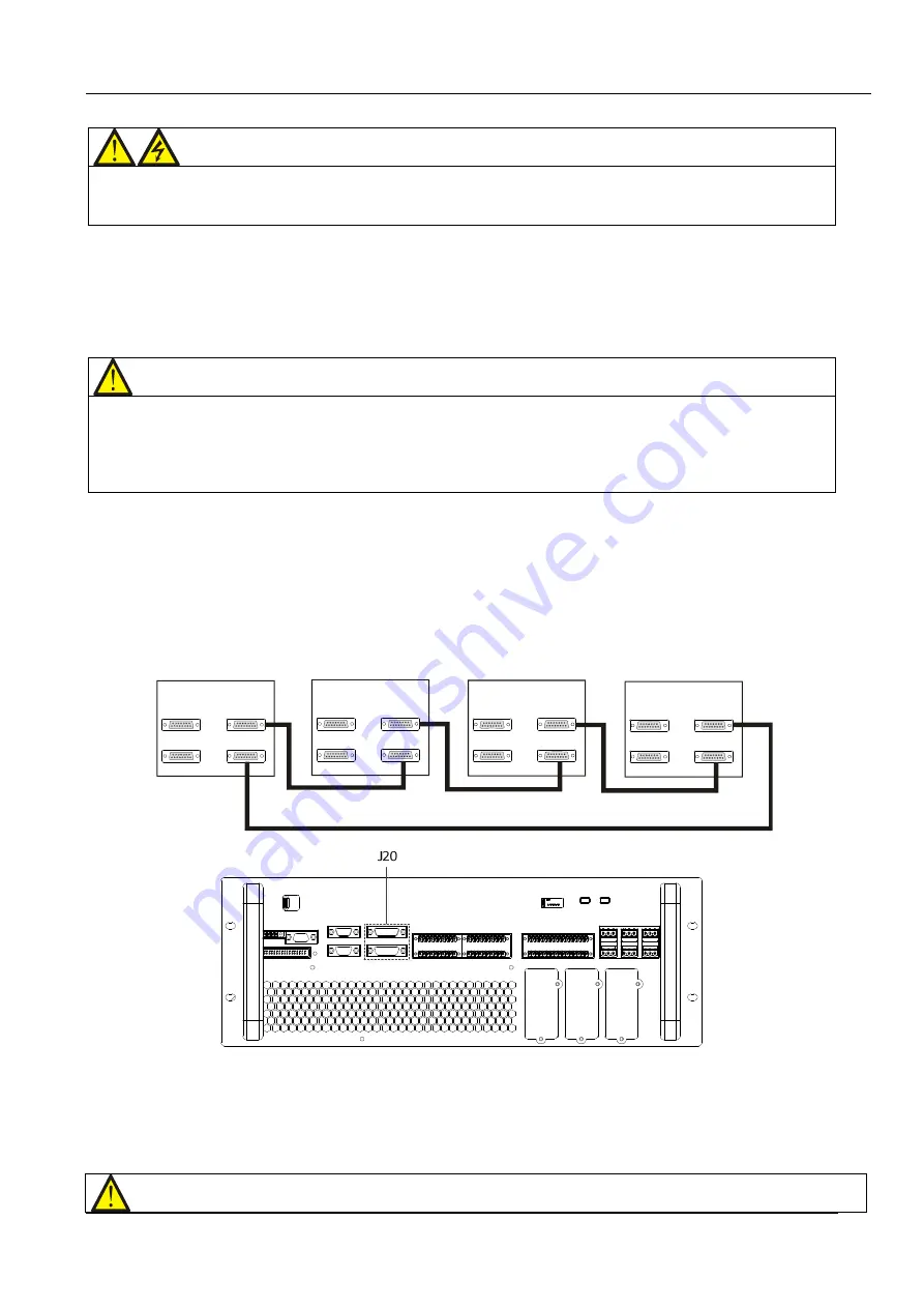
The shielded, double-insulated parallel cables, available in lengths of 5m, 10m and 15m, must be interconnected in
a ring configuration between the UPS modules, as shown in Figure 8-2.
To do this, connect a parallel cable between the PARA1 port of the first module to the PARA2 port of the next
module and continue in this way until all the modules have been connected and the ring has been formed by
connecting the PARA1 port of the last module to the PARA 2 port of the first.
The parallel port J20 is located on the front panel of the bypass module, as shown in Figure 8-3.
Connecting the modules in a ring configuration ensures the reliability of the control of the parallel system. Make
sure that all the cables have been connected securely before starting the system!
UPS 1
UPS 2
UPS 3
UPS 4
LBS 1
PARA 1
LBS 2
PARA 2
LBS 1
LBS 2
PARA 1
PARA 2
LBS 1
LBS 2
PARA 2
LBS 1
LBS 2
PARA 1
PARA 2
PARA 1
UPS 1
UPS 2
UPS 3
UPS 4
Figure 8-2 Parallel signal cable connections (Parallel system)
Figure 8-3 Location of parallel port J20 on bypass module
8.2.6
Remote EPO
In addition to the EPO switch on the operator control and display panel of each UPS, which is used to activate the
EPO function on the individual module, the parallel system also includes a remote EPO function that can be used
to shut down all the UPS modules simultaneously via a remote terminal, as shown in Figure 8-4.
Note


