User Manual 10H52258UM60 - Rev. 3 - 01/2019
76
APM 400/600
Parallel System and LBS System
exceed the power rating of a UPS module system.
8.5
External Protection Device
Refer to Section 4.1.8 in Chapter 4 for information about installing External Protection Devices.
8.6
Power Cable
The power cable of a dual-bus power system is similar to that of a single system. (Refer to section 4.1 Power
Cable Wiring for details).
The bypass and rectifier input supplies should use the same neutral line input terminal.
Note
An input may be fitted with a current leakage protection device. If so, the device must be fitted upstream of the
neutral line input terminal.
8.7
LBS cable
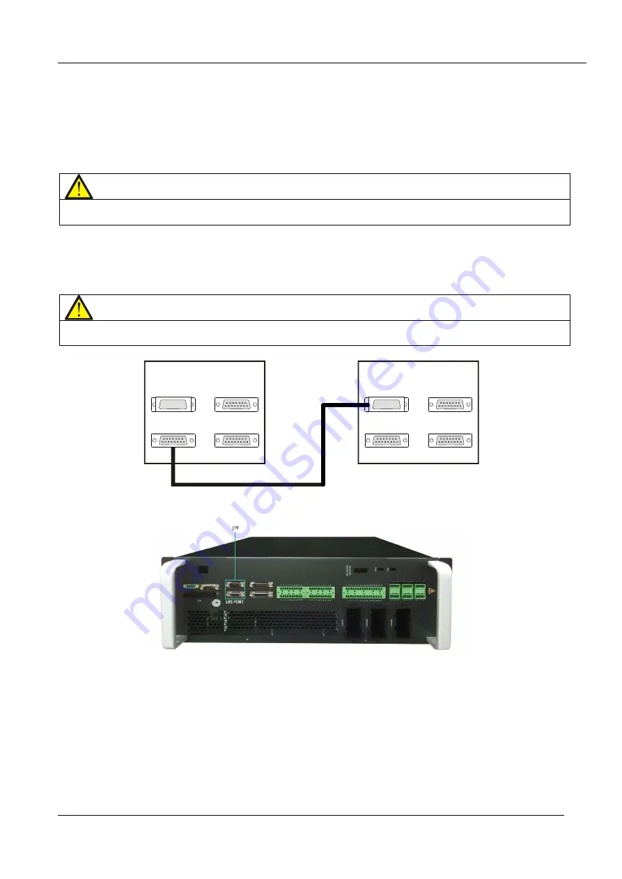
In the case of a dual bus system, connect the optional LBS cables (10m, 15m, and 20m) between the LBS ports
(J19) on the two UPS systems, as shown in Figure 8-6. The J19 ports are located on the front panel of the bypass
module, as shown in Figure 8-7.
Note
The LBS cables should be kept as short as possible. Avoid excess coiling, and route the LBS cables separately
from the power cables in order to prevent electrical interference.
UPS 1
PARA 1
PARA 2
LBS 1
LBS 2
UPS 2
PARA 1
PARA 2
LBS 1
LBS 2
LBS
电 缆
UPS 1
UPS 2
LBS cable
Figure 8-6 Connecting a typical LBS system (UPS module)
Figure 8-7 LBS port (J19) on the bypass module
8.8
LBS Adapter
The LBS Adapter box is designed to extend the LBS function up to 150m between the UPS modules or systems of
a dual bus system. It also enables an APM UPS to synchronize with the other UPS models.


