background image

User Manual 10H52258UM60 - Rev. 3 - 01/2019 

82


APM 400/600 

Optional Components 

Yellow  LED.  On  =  The  LBS  adapter  is  connected  to  a  non-APM  UPS;  Off  =  The  LBS  adapter  is 
connected to an APM UPS 

SWITCH 

The switch should be placed to right if the LBS adapter is connected to an APM UPS and to left if the 
LBS adapter is connected to a non-APM UPS 


Parameter 

Specification 

Voltage 

120 Vac ~ 277 Vac 

Frequency 

45 Hz ~ 65 Hz 

Current 

1.5 A max. 

 
Electrical Parameters 
 
See Table 9.3 below for the LBS adapter electrical parameters 
 
Installation 

Note 

Before discussing the installation process, remember that only qualified and trained personnel are allowed to install 
the LBS adapter due to the hazardous voltage that may exist at the UPS output terminals. 

 
Mounting the LBS adapter 
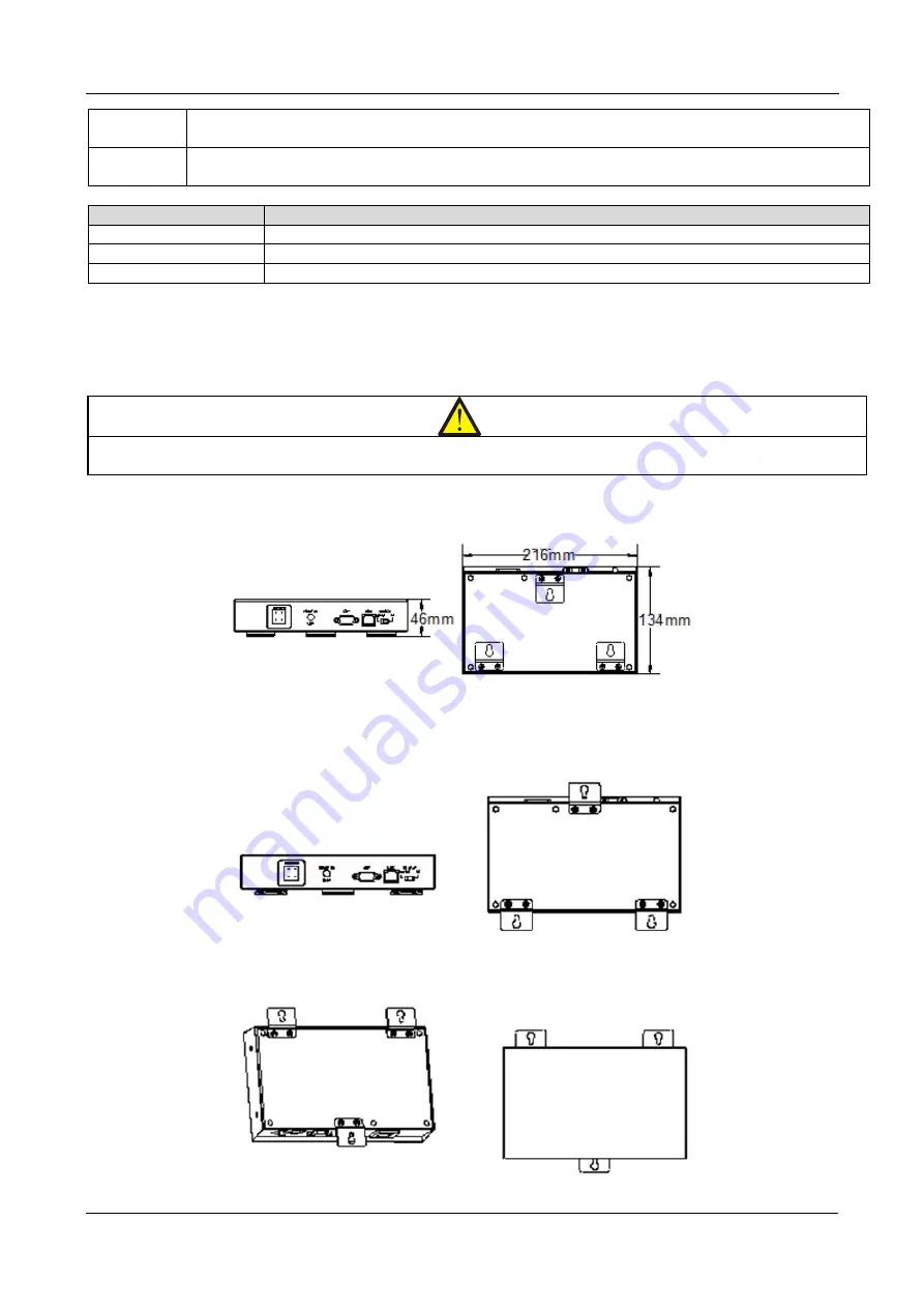
The dimensions of the LBS adapter are indicated in Figure 9-6. 


Figure 9-6 LBS adapter dimensions 

 
The LBS adapter may be installed horizontally or vertically, as indicated in Figure 9-7. 
 
Horizontal installation 


Vertical Installation 


Figure 9-7 Horizontal and Vertical installation 

Summary of Contents for Liebert APM 400

Page 1: ...Liebert APM 400 600kW User Manual ...

Page 2: ...APM 400 600 UNINTERRUPTIBLE POWER SUPPLY USER MANUAL 10H52258UM60 rev 3 ...

Page 3: ......

Page 4: ...e liable for damages All rights including rights deriving from the granting of patent or registration of utility model or design are reserved Delivery subject to availability The Manufacturer reserves the right to make changes and or improvements to the product without prior notice and without incurring obligations APM 400 600 may differ from the model displayed on the front cover ...

Page 5: ...ever attempt to dispose of the internal and external batteries in fire as they may explode leading to serious injuries or even death Product Safety 1 If the product is to be stored or unused for extended periods place the equipment in a clean dry environment within the specified temperature range 2 Consult the Site Preparation section for information about the ideal operating and maintenance envir...

Page 6: ...s present on the unit as well as those included in the manual In addition installation restrictions or additional measures may be required to prevent disturbance Conformity and standards The UPS complies with 2014 35 EU low voltage safety and 2014 30 EU with Australia and New Zealand EMC Framework C Tick and with the following UPS product standards IEC EN 62040 1 A1 2013 general and safety require...

Page 7: ...rvicing procedures involving access to the internal parts of the equipment require the use of a tool and should be carried out by qualified and trained professionals only None of the user serviceable parts located behind the covers require a tool or key for removal Battery voltage exceeds 400Vdc All physical battery maintenance and servicing procedures require the use of a tool key Such tasks shou...

Page 8: ...5 User Manual 10H52258UM60 Rev 3 01 2019 APM 400 600 The Manual Covers the Following Devices Product Model APM 400 APM 0400kTK16FN01000 APM 600 APM 0600kTK16FN01000 ...

Page 9: ...LCD Screen Type 37 5 7 Start Screen 37 5 8 Detailed description of the various menu items 38 6 An introduction to the UPS operating procedures 47 6 1 Precautions and Safety measures 53 6 2 Power Switch 54 6 3 UPS Start up Procedure 54 6 4 Procedure for transferrring between operating modes 56 6 5 Battery Test Procedures 57 6 6 UPS Shutdown Procedures 58 6 7 EPO procedures 59 6 8 UPS Reset Procedur...

Page 10: ...6 9 Optional Components 77 9 1 Introduction to the Optional components 77 10 Service Maintenance 84 10 1 Power Module and Bypass Module service procedures 84 10 2 Key Components and UPS Service Life 85 10 3 Maintenance of UPS and Options 87 11 Specifications 88 11 1 Conformance and Standards 88 11 2 Environmental Specifications 88 11 3 Mechanical Specifications 88 11 4 Electrical Specifications In...

Page 11: ...PM series supplies power free of the disturbances and voltage and frequency variations that typically affect utility power which is subjected to brownouts blackouts surges and sags Increases in capacity and redundancy can be made both vertically and horizontally by adding power modules to an existing rack alternatively it may be achieved by connecting complete UPS systems in parallel in order crea...

Page 12: ... flammable concrete surface The environment should be free from conductive powders such metallic dust sulfide sulfur dioxide graphite carbon or conductive fibers etc acid mist or other any conductive media any strongly ionized substance The environmental specifications should comply with the international standards and specifications within the pre defined operating range as displayed in the follo...

Page 13: ...e the battery is positioned at a distance from the UPS the battery circuit breaker shall be installed near the battery In such situations the connecting cables must be designed to be as short as possible 2 1 3 Storage In the event that the UPS is not to be installed immediately following delivery is must be stored in the original packaging in an environment where it is protected from excessive hum...

Page 14: ...age reaches 320Vdc which can cause severe injury and may even be fatal to personnel if not handled properly The following is a list of safety measures that must be observed while connecting or handling the batteries Wear safety glasses to protect the eyes from arcing Remove all metal and conductive items such as rings and watches Use insulated tools and rubber gloves Replace any batteries that may...

Page 15: ...s or abnormalities are detected contact your local Vertiv service center 3 2 Tools This section looks at the most commonly used tools for these procedures The tools mentioned in this section are for reference only select the appropriate tools after taking the on site installation procedures and connections into consideration Warning Ensure that the tools used when installing operating and servicin...

Page 16: ...able 3 1 Name Drawing Name Drawing Electric hand drill Adjustable wrench Slotted screwdriver Cross head screwdriver Stepladder Forklift Drill Wire cutting pliers Claw hammer Diagonal cutting pliers Insulating shoes Antistatic gloves Electrician knife Cable tie Insulating tape Insulating gloves Crimping pliers Heat shrinkable tube Insulated torque wrench Torque screwdriver Multimeter Clip on ammete...

Page 17: ...y step procedure for unpacking the units 1 Remove the packing straps and honeycomb boards as shown in Figure 3 2 Figure 3 2 Removing the packing straps and honeycomb boards 2 Remove both the front and rear kick plates Figure 3 3 displays the position of the kick plates Figure 3 3 APM UPS kick plates during unpacking 3 Remove the fixing bolts at the bottom of the cabinet See Figure 3 4 for the loca...

Page 18: ...efined in the product technical specifications The previous section covers the UPS and battery unpacking procedures the equipment should be unpacked under the guidance of the authorized service personnel and trained engineers The final step in the initial check up is to verify the UPS label and ascertain if everything is in place To confirm that the UPS complete and correct refer to the UPS label ...

Page 19: ...t The center of gravity of the UPS cabinet is high make sure that it is secured against tipping when moving it The cabinet must not be suspended vertically Note Cabling is another fundamentally important aspect of the installation procedure The UPS uses both top and bottom cable access methods This topic will be discussed in detail in the Electrical Installation section 3 6 Installing and removing...

Page 20: ...sh it into the cabinet 3 Secure the module to the cabinet via the mounting holes on either side of the front panel of the module 4 Set the ready switch to the Down position the Down position corresponds to the ready state 3 7 Installation Drawings This section contains the installation drawings which indicate the dimensions of the APM 400 600 MODULAR UPS For an overall picture of the dimensions it...

Page 21: ...l Installation Figure 3 7 Top Bottom Front Side View and Dimensions units mm APM 400 Top cabling area 550 350 Top view door open Air outlet Air inlet Front view Side view Bottom cabling area 550 350 Cabling hole A foot installation hole A Amplified view Bottom view ...

Page 22: ...19 User Manual 10H52258UM60 Rev 3 01 2019 Mechanical Installation APM 400 600 Figure 3 8 Bottom View showing Seismic Anchors and Dimensions APM400 Bottom view ...

Page 23: ...User Manual 10H52258UM60 Rev 3 01 2019 20 APM 400 600 Mechanical Installation Figure 3 9 Top Bottom Front Side View and Dimensions units mm APM 600 ...

Page 24: ...nual 10H52258UM60 Rev 3 01 2019 Mechanical Installation APM 400 600 500 142 5 1070 1020 500 500 500 1785 1785 500 500 142 5 8 Φ15 Bottom view Figure 3 10 Bottom View showing Seismic Anchors and Dimensions APM 600 ...

Page 25: ...scharge current requirement as it reaches the EOD voltage Refer to Table 4 1 Table 4 1 4 1 2 Maximum Steady State AC and DC current The battery cables must be selected based on the current and voltage indicated in Table 4 1 Adhere to the local wiring regulations and take environmental conditions such as temperature and other physical factors in to consideration Refer to the table 3B in IEC 60950 1...

Page 26: ...vel Cable length and Protection Type The earth connection cable must be designed to be as short as possible In the case of large currents it may be easier to use multiple cables with smaller cross sections in order to simplify the installation process When selecting the cross section of the battery cable in addition to the values indicated in Table 4 1 it is also necessary to take the maximum volt...

Page 27: ...uch devices are required in order to comply with local regulations it is important to be aware that if separate differential circuit breakers DCB are installed on the input and bypass power lines they may trip unexpectedly interrupting the power supply to the unit Therefore if it is necessary to install a DCB a single device should be used for both the primary and bypass inputs In the case of IT n...

Page 28: ...fer from that installed on the input distribution line and be capable of providing overload protection Refer to the Appendix section for the Electrical Specifications of the Intermediate DC Circuit and Inverter Output Note In the case of IT networks the UPS external input power distribution line must be fitted with a 4 pole protective device 4 1 9 Power Cable Connection steps Following is a list o...

Page 29: ...terminals of 400 600kVA Note The power cables should be routed through conduits or cable troughs in order to prevent damage due to mechanical stress as well as reducing Electromagnetic Interference EMI When routing the cables inside the cabinets they must be tied and secured so as to prevent any damage from mechanical stress ...

Page 30: ... cable access Figure 4 4 Power cables wiring route bottom cable access Warning Ensure that all internal and external UPS power switches are set to the OFF position before connecting the cables Post the necessary warning signs and labels in order to prevent inadvertent operation of the switches Top cable access Bottom cable access ...

Page 31: ...guration the supply to the UPS mains and bypass input terminals will be interrupted if the upstream circuit breaker trips Split bypass configuration Factory default Connect the rectifier input cables to the rectifier input terminals mA mB mC in the cabinet Connect the bypass input cables to the bypass input terminals bA bB cC in the cabinet Next connect the rectifier input neutral line and the byp...

Page 32: ...The communication box includes the following ports as shown in Figure 4 5 1 EPO Port 2 RS232 Communication Port 3 LBS Communication Port 4 Parallel Communication Port 5 User Dry contact Port 6 Intellislot Port 4 2 2 Port J21 Figure 4 6 illustrates the Port J21 This port which is reserved for operated trained authorized Service Engineers only is used to configure the parallel CAN bus When the UPS i...

Page 33: ... 5 GND_DRY Dry ground 6 NC Reserved 7 BCB_ONLine BCB on line signal 8 NC Reserved 9 NC Reserved 10 NC Reserved 11 GND_DRY Dry ground 12 NC Reserved 13 TMP_BAT External battery temperature 14 NC Reserved 15 12V_DRY Power 16 NC Reserved 17 GND_DRY Dry ground 18 NC Reserved 19 BAT_Ground_FAULT Battery ground fault 20 NC Reserved Note The BCB drive signal and external battery temperature signal cables...

Page 34: ...d terminal 8 12V_DRY Reserved 9 Q3 STATUS External maintenance switch status signal 10 Reserved Reserved 11 GND_DRY External maintenance switch status signal ground terminal 12 GND_DRY Reserved 13 Q5 STATUS External output switch status switch 14 ENV_DET Battery room temperature abnormal 15 GND_DRY External output switch status signal ground terminal 16 GND_DRY Battery room temperature abnormal gr...

Page 35: ...tate normally open contact Closed when the rectifier is on 3 MFP_S Rectifier back feed common contact 4 MAIN_S Rectifier input state common contact 5 MFP_C Rectifier back feed normally closed contact Closed when there is no back feed 6 MAIN_C Rectifier input state normally closed contact Open when the rectifier is off J25 1 RESV_O Reserved 2 RESV_O Reserved 3 RESV_S Reserved 4 RESV_S Reserved 5 RE...

Page 36: ...he RS232 communication port This port can be used to monitor and set up parameters when connected to a computer The RS232 port communication port provides serial data and is intended for use by authorized commissioning and service personnel when commissioning and servicing the UPS 4 2 8 Parallel and LBS Communication Port See Figure 4 5 for the position and location of these ports 4 2 9 Intellislo...

Page 37: ...rrect position The signal cable shield must be earthed securely There are two signal cable connection options Top cable access Bottom cable access Refer to Figure 4 11 and Figure 4 12 for the cabling route and then connect the signal cables to their respective ports as indicated in Figure 4 5 Figure 4 11 Top cable access for Signal cable wiring Figure 4 12 Bottom cable access for Signal Cable wiri...

Page 38: ...e 5 1 illustrates the power flow chart LCD display with the menu keys and the control keys For a description of the various functions see Table 5 1 below Figure 5 1 Operator Control and Display panel Table 5 1 No Function 1 Rectifier Indicator 2 Battery Indicator 3 Bypass Indicator 4 Inverter Indicator 5 Output Indicator 6 Status Indicator 7 Buzzer Key Function F1 to F4 LCD Menu Keys HELP LCD Menu...

Page 39: ...onal Output indicator Solid green UPS output On and Normal Solid red UPS output On and Overloaded Off UPS output off Status indicator Solid green Normal operation Solid yellow UPS alarm for example no battery Solid red UPS fault for example fuse or hardware fault 5 3 Audible Alarm Buzzer The Buzzer or the UPS activity is associated with the two different sounds described in Table 5 3 Table 5 3 Ala...

Page 40: ...p Function 1 Function 2 Thanks to its 320 240 dot matrix graphic display the user friendly menu driven LCD enables users to browse through the UPS input output load and battery parameters with ease as well as accessing UPS status and alarm information as well as performing functional settings and control operations The LCD can also store up to 2048 historical records which can be retrieved for ref...

Page 41: ...to access the Output menu 5 7 2 Default screen During the normal operation if no alarms are active and no actions are performed the default screen is displayed see Figure 5 4 Figure 5 4 Default screen After a certain length of time if no actions are carried out and no alarms are active in default screen mode the LCD backlight will switch off similar to a smart phone touch screen where the screen s...

Page 42: ...he Menu window and Data window helps users when browsing through the UPS parameters and setting up the UPS functions Table 5 7 below lists the menu items complete with a short description Table 5 7 Menu Item Description Mains L N voltage V Phase voltage L N current A Phase current Frequency Hz Input frequency L L voltage V Line voltage Power factor Power factor Bypass L N voltage V Phase voltage F...

Page 43: ... DD MM YYYY YYYY MM DD Date time Sets the date and time Comm1 baud rate Sets the Intellislot port 1 communication baud rate Comm2 baud rate Sets the Intellislot port 2 communication baud rate Comm3 baud rate Sets the Intellislot port 3 communication baud rate Communication address Applicable to RS485 communication Single Group Batt Cap Sets the capacity of battery unit Battery Cells Number Sets th...

Page 44: ...test manually Top up charge This command may be used to initiate a battery top up charge manually Stop top up charge This command may be used to interrupt a battery top up charge manually Modem automatic response activated Modem automatic response activated setting Eff Curve Eff Curve Displays the system efficiency at current load Run Time UPS Run time Displays the accumulated UPS run time Byp Run...

Page 45: ...ttery self test condition is not met Please check if the battery is in boost charge state and the load is greater than 20 of the nominal value Battery Top up Charge aborted conditions not met This prompt appears when the user selects the top up charge command when battery top up charge conditions are not met e g no battery charger failure 5 8 5 Alarm List Table 5 9 below describes all the alarm me...

Page 46: ...until the system is powered down Byp Abnormal Shutdown Both the bypass and inverter voltages are abnormal and the output is off Bypass Phase Reversed The phase rotation of the bypass voltage is reversed Bypass overcurrent The bypass current is out of tolerance Bypass backfeed The bypass back feed is faulty Bypass Over temperature There is an over temperature condition on the Bypass Bypass in Charg...

Page 47: ...nd display panel has been pressed or a remote EPO command has been received Fan Abnormal At least one fan is faulty Operation Invalid The maintenance bypass switch is closed when the parallel system is on inverter or the output and maintenance bypass switches are closed when the inverter is running LBS Active The LBS setting is active LBS Abnormal LBS is abnormal Input Switch Open The input switch...

Page 48: ...unication failure between racks PowerCAN Comm Abnor Communication failure between inverter rectifier and bypass ParaPowerCANCommAbnor Communication failure between different UPSs in parallel system Check if any of the UPS units are de energized or if any of the parallel cables are not connected correctly then clear the fault in order to restart the UPS Discr BusComm Abnor Communication failure on ...

Page 49: ...nside the rack are connected reliably and that the bypass module is secured properly Ambient Overtemp The ambient temperature over limit threshold this value may be set up using the configuration software Byp SCR Fan Abnormal The internal bypass module fan is faulty Top outlet Fan Abnor The top air outlet fan is faulty System Interrupt Xfer Execute the interval transfer under conditions of bypass ...

Page 50: ...hin normal operating limits the rectifier and inverter work together to supply the loads and charge the battery When the mains is outside these limits the rectifier stops working and the battery supplies power to the loads via the inverter If the battery voltage reaches the End Of Discharge EOD voltage and the mains power supply has still not been restored the UPS will shut down if the system uses...

Page 51: ...lly and the UPS operator control and display panel will display the corresponding alarm messages If the system uses split bypass configuration and the bypass is normal the system will transfer to bypass Mains recovery If the mains supply returns within normal operating limits within the permissible time the rectifier will restart automatically supplying the load and charging the battery again In t...

Page 52: ...the ON position and disconnected by turning it to the OFF position UPS Power Supply Switch Configuration The UPS is equipped with four switches the rectifier input switch Q1 bypass input switch Q2 maintenance bypass switch Q3 and output switch Q5 Note Switches Q1 Q2 and Q5 are optional whereas switch Q3 is fitted on the standard configuration Figure 6 2 illustrates the block diagram of the UPS mod...

Page 53: ...ser with maximum flexibility For example UPS modules in a parallel system may be shut down or started up in any sequence Transfers between normal and bypass modes of operation are synchronized and self recoverable after events such as overloads have been cleared 3 The total load of the parallel system can be queried from the LCD on each module Parallel System Requirements A group of modules connec...

Page 54: ...he EOD voltage if and when the mains supply recovers the UPS will restart following a predetermined delay period This function and the automatic restart mode must be set up by an authorized Vertiv engineer During the automatic restart process following the predetermined delay the UPS will recharge the battery to guard against the risk of interruptions in the power supply to the load in the event o...

Page 55: ...he mains input ECO mode In ECO mode all the power switches and battery switches are closed except for the maintenance bypass switch and the system prioritizes the bypass as the preferred source for the load power in order save energy When the bypass supply frequency and voltage are within the normal operating limits adjustable the load is powered by the bypass while the inverter remains on stand b...

Page 56: ...ry mode UPS modules that are connected in parallel share the same battery string in order to reduce costs save space and improve efficiency Note All batteries used in the same system must be identical same manufacturer same model same age 6 1 Precautions and Safety measures This section describes the precautions and safety measures that personnel handing the UPS must adhere to in order to prevent ...

Page 57: ... UPS Start up Procedure The UPS must be installed completely and tested by an authorized engineer or personnel Initially the external power supply switch should be closed after which the UPS may be started 6 3 1 Start up in Normal mode This section provides a detailed description of the start up process in Normal operating Mode Warning Prior to the Start up process remember that the start up proce...

Page 58: ...ttery switch once the rectifier light assumes the steady green state Then press and hold the Inverter On key for a period of 2 seconds The Inverter indicator displays a flashing green color once the inverter has been started Once the inverter is running normally the UPS switches from the bypass mode to the Inverter mode Finally after a short delay the Inverter indicator switches to the steady gree...

Page 59: ... few seconds and then close the external input power switch in order to reconnect the mains input to the UPS After a delay of 10 15 seconds the rectifier starts automatically and the UPS reverts to normal mode 6 4 2 Transfer from Normal mode to Bypass mode To switch the UPS from the Normal mode to bypass mode press the INVERTER OFF key for a period of 2 3 seconds A pop up window is displayed on th...

Page 60: ...tor assumes the steady green state At this point the rectifier starts running and the UPS switches to Bypass Mode Open the maintenance bypass switch Q3 Upon completion of the rectifier start up process the rectifier indicator assumes the steady green state Close the external BCB and press the INVERTER ON key until the inverter starts Once the Inverter indicator assumes the steady green state the U...

Page 61: ... stop the maintenance test manually at any time via the LCD Note If the self test is completed successfully the system will fully reset the self test interval counter However if the self test fails then it exits the system when the self test conditions are satisfied again then it enters self test mode once more 6 5 4 Manual maintenance self test procedures The following is a list of instructions t...

Page 62: ... normal workflow If the system has been shut down due to a critical fault the fault will generate an audible visual alarm and an alarm message will be displayed on the LCD screen Clear the fault by following the instructions in the specific alarm message On occasions the UPS may be shut down by the EPO function in the event of a natural disaster or critical situation In either case it is necessary...

Page 63: ...utput menu screen press the F3 left or F4 right key to select the Language menu Press the HELP Enter key to move the cursor to the screen data window Press the F3 up or F4 down key to select the desired language Press the HELP Enter key to continue Press the F2 ESC key to return repeatedly to return to the Output menu At this point the LCD displays all the menus in the selected language 6 11 Chang...

Page 64: ... a number between 0 and 9 in this position Enter 5 digits in this way and then press HELP enter to confirm At this stage the Password management command changes to Enter New Password Press the F3 and F4 to enter the new password as described above and then press the HELP Enter key to confirm At this point the Password management command changes to Enter New Password again Enter the new password ag...

Page 65: ... to carry out maintenance work on any given string without affecting the normal operation of other battery strings 7 2 Safety Precautions This section covers the various precautions and safety measures that should be observed when working with and handling UPS batteries Users must adhere strictly to the measures included in this section in order to avoid severe injury or damage to the equipment Wa...

Page 66: ...ould be handled and moved carefully in order to avoid personal injuries and damage to the equipment Severe damage to the battery may result in fires Avoid applying forces such as cable pulling or twisting forces to the battery terminals since doing so could damage the internal battery connections resulting in the risk of fires The batteries should be installed in clean cool dry place Avoid install...

Page 67: ...tion Another factor for consideration is that the valve regulated batteries are not entirely maintenance free They must be kept clean and inspected on a regular basis The connections must be checked and inspected for signs of corrosion For more information see the Battery Maintenance section No more than 4 strings of batteries should be connected in parallel All batteries used in the same system m...

Page 68: ...ture The higher the temperature the shorter the battery service life will be At a low temperature the change discharge performance of the battery will be reduced significantly For optimum results the battery must be installed in a cool dry environment where the relative humidity is less than 90 and away from heat sources and or direct sunshine Battery temperature is dependant on ambient temperatur...

Page 69: ...tall and connect the batteries Reliable insulated tools are mandatory to ensure safety of the personnel 7 6 1 Installing the Batteries The following steps must be taken into consideration before installing the batteries Check the batteries visual inspection for signs of damage Inspect the accessories supplied with the batteries Count the accessories to see if anything is missing Read this manual c...

Page 70: ...iddle layer Bottom layer BCBN BCB Figure 7 4 Battery connections 7 7 Battery room design Irrespective of the installation type the points listed below must be taken into account when designing the battery room Figure 7 5 illustrates the design of the battery room Figure 7 5 Battery room design Layout of the cells Workbench Wiring BCB Layout of the cells Irrespective of the battery installation typ...

Page 71: ... 1640 Reference rated current of BCB A 1300 2000 CSA of connection cable mm2 3 x 240 4 x 240 42 block battery Maximum battery discharge current at full load A 1040 1560 Reference rated current of BCB A 1300 2000 CSA of connection cable mm2 4 x 185 4 x 185 44 block battery Maximum battery discharge current at full load A 993 1490 Reference rated current of BCB A 1300 1600 CSA of connection cable mm...

Page 72: ...ies Place any leaky or damaged batteries in a container capable of withstanding sulfuric acid and dispose of it according to the local rules and regulations Used lead acid accumulator batteries are classified as hazardous waste and must be stored transported used and disposed of in accordance with the national and local regulations on dangerous waste in addition to the standards covering the preve...

Page 73: ...em This section only covers the installation procedures that are specific to the parallel system To install a parallel UPS system carry out the installation procedure for a single UPS module plus the additional operations described in this section 8 2 1 Preliminary Checks Make sure that the parallel cable options are correct and that the modules are identical same rating same model and same softwa...

Page 74: ... double insulated parallel cables available in lengths of 5m 10m and 15m must be interconnected in a ring configuration between the UPS modules as shown in Figure 8 2 To do this connect a parallel cable between the PARA1 port of the first module to the PARA2 port of the next module and continue in this way until all the modules have been connected and the ring has been formed by connecting the PAR...

Page 75: ... the top of Figure 8 4 whereas the Normally Closed version s shown at the bottom 8 3 Operation Procedures For Parallel Systems Warning If UPS input uses RCDs the differential switch is only used in the system bypass mains supply At the moment when the electrical power supply is connected the current may not be separated immediately which may result in the respective RCCB tripping This procedure sh...

Page 76: ... Maintenance Bypass Procedures Warning If the UPS system consists of more than 2 parallel UPS modules and the load capacity exceeds the single module capacity do not use the internal maintenance bypass switch This operation will transfer the load from the protected UPS output power supply so that it is connected directly to the AC input bypass supply Caution Danger of interruption in power supply ...

Page 77: ...ion 3 Connect the remaining parallel cables correctly to the other modules refer to 8 2 5 Parallel Cables Warning 1 Post a label at the AC input distribution point normally located at a distance from the UPS to notify other personnel that the UPS maintenance is in process 2 Wait for 10 minutes for the internal DC bus capacitor to discharge so that the UPS is completely de energized 8 3 4 Procedure...

Page 78: ...hut the UPS down completely while maintaining the power supply to the load Refer to the procedures in 8 3 2 Maintenance Bypass Procedures 8 4 Installing the Cabinet A LBS system consists of 2 independent UPS systems each containing one or more parallel UPS modules as illustrated in Figure 8 5 The LBS system provides ultra high reliability and is ideally suited to loads with multiple inputs In the ...

Page 79: ...minal 8 7 LBS cable In the case of a dual bus system connect the optional LBS cables 10m 15m and 20m between the LBS ports J19 on the two UPS systems as shown in Figure 8 6 The J19 ports are located on the front panel of the bypass module as shown in Figure 8 7 Note The LBS cables should be kept as short as possible Avoid excess coiling and route the LBS cables separately from the power cables in ...

Page 80: ...loat voltage supplied to the battery is regulated since it is inversely proportional to the ambient temperature of the cabinet or battery room This prevents the battery from being over charged at a high ambient temperature Preparation Prepare the installation tools including a cross head screwdriver Confirm if all the installation materials are present and complete including a battery temperature ...

Page 81: ...to do so may result in damage to the UPS and the inductors 1 Set all the power switches e g battery and load to the OFF position 2 All the LCDS are off wait five minutes for the UPS internal DC bus capacitors to discharge completely 3 Remove all the screws connecting the 400 kVA power cabinet and power distribution cabinets together Then remove the 400 kVA power cabinet and its rear panel Keep the...

Page 82: ...he card it is hot pluggable Warning Some electronic components on the Unity card are sensitive to static therefore in order to avoid subjecting it to static shock avoid touching the Unity card components or circuits using bare hands or conductive materials When removing or installing the Unity card hold it by the edges The Unity card should be installed in the Intellislot port see Figure 3 3 in th...

Page 83: ...ypass Low Battery Summary Alarm UPS Fault and On UPS signals this easy to install card integrates with AS 400 computers additional cable required and other relay contact monitoring systems The relay card is rated for 24 VAC DC at 1A The IS Relay card is illustrated in Figure 9 4 Figure 9 4 IS Relay card The UPS IS Relay card option provides dry contact signals that may be used to monitor the UPS T...

Page 84: ...ing 1 The terminal block connectors must be connected to a SELV circuit Failure to observe this could damage the relay card and even lead to accidents 2 The external equipment must meet the electrical parameter requirements set out in Table 8 2 failure to observe this could cause damage to the dry contact output terminal For more detailed information about this utility refer to the Liebert Intelli...

Page 85: ... A max Electrical Parameters See Table 9 3 below for the LBS adapter electrical parameters Installation Note Before discussing the installation process remember that only qualified and trained personnel are allowed to install the LBS adapter due to the hazardous voltage that may exist at the UPS output terminals Mounting the LBS adapter The dimensions of the LBS adapter are indicated in Figure 9 6...

Page 86: ...BS adapter connected to the non APM UPS 3 Connect the communication cable up to 150m to the COM2 port on each LBS adapter 4 Set the switch on the LBS adapter connected to the APM UPS to the right position 5 Set the switch on the LBS adapter connected to the non APM UPS to the left position The circuit diagram in Figure 9 9 illustrates the connection between the 2 LBS adapters in the case of an APM...

Page 87: ...e power modules and bypass modules from top to bottom to prevent the cabinet from toppling over due to higher center of gravity To ensure safety before servicing the power module and bypass module use a multi meter to verify and confirm that the bus capacitor voltage is lower than 60 Vdc and that the potential difference between the components to be serviced and the UPS earth connection are less t...

Page 88: ...ed and the green indicator is illuminated Press the FAULT CLEAR key so that the module reconnects to the system automatically When the bypass indicator assumes the steady green state it indicates that the UPS is in Bypass mode Open the Maintenance bypass switch Bypass Control module service procedure in normal mode Set the ready switch on the front panel of the power module to the UP position i e ...

Page 89: ... at regular intervals These intervals are determined based on the environmental conditions in the area where the UPS is installed In normal environmental conditions the air filters should be cleaned or replaced every 2 months If the surroundings are dusty or affected by of high levels of dirt and other airborne contaminants more frequent cleaning and replacement is required Filters should also be ...

Page 90: ...apacity significantly Similarly excessively high temperatures will reduce its working life Wiring must be inspected regularly to guarantee uninterrupted operation and good service life Inspect the connection screws on a monthly basis and check the tightening torque once every six months Carry out a functional test on the switches install up and down stream of the UPS at regular intervals to make s...

Page 91: ...corporate relevant compliance clauses with generic IEC and EN standards for safety IEC EN AS60950 electromagnetic emission and immunity IEC EN AS61000 series and construction IEC EN AS60146 series and 60529 11 2 Environmental Specifications Item Unit Rated power kVA 400 600 Noise within 1m in the front dB A 70 Altitude m 1500 derate power by 1 per 100m between 1500m and 3000m Relative humidity RH ...

Page 92: ...voltage at nominal value and voltage distortion THDV 1 5 Measured with an input THDv 1 11 5 Electrical Specifications Intermediate DC Circuit Item Unit Rated power kVA 400 600 Max charging current A 101 151 Rated battery bus voltage Vdc 456 528 Quantity of lead acid cells nominal Block 38 44 12 Vdc Float voltage V cell VRLA 2 25 selectable from 2 2 V cell to 2 3 V cell Constant current and constan...

Page 93: ...voltage1 Vac 380 400 415 3 phase 4 wire sharing neutral with the rectifier input and providing neutral reference to the output Rated current 380V 400V 415V A 909 A 866 A 835 Frequency2 Hz 50 60 Bypass voltage tolerance Vac Upper limit 10 15 or 20 default 15 Lower limit 10 20 30 or 40 default 20 bypass voltage normalization acceptance time 10s Bypass frequency tolerance 10 or 20 default 10 Recommen...

Page 94: ...PO Emergency Power Off I O Input Output IGBT Integrated Gate Bipolar Transistor LBS Load Bus Synchronizer LCD Liquid Crystal Display LED Light Emitting Diode MCCB Molded case Circuit Breaker PC Personal Computer PE Protective Earth PWM Pulse Width Modulation RCCB Residual Current Circuit Breaker RCD Residual Current Detector REPO Remote Emergency Power Off SCR Silicon controlled Rectifier SNMP Sim...

Page 95: ...nces due to the lack of reliable or suitable alternatives 1 All solder used in the products contains lead 2 Copper alloy contains lead 3 Backlight bulb contains mercury 4 The ceramic capacitor parts and copper terminals and leads used on metallic film capacitors contain lead 6 The LCD glass screen contains lead and the backlight lamp contains mercury 7 The level of performance required by the syst...

Page 96: ... out wheelie bin symbol on the right is placed on this product to encourage you to recycle wherever possible Please be environmentally responsible and recycle this product at your local recycling facility at its end of life Do not dispose of this product as unsorted municipal waste Follow local municipal waste ordinances for proper disposal provisions to reduce the environmental impact of waste el...

Page 97: ... of Vertiv Co All other names and logos referred to are trade names trademarks or registered trademarks of their respective owners 2017 Vertiv Co All rights reserved VertivCo com Vertiv Infrastructure Limited George Curl Way Southampton SO18 2RY VAT Number GB188146827 ...

Reviews: